Damaged pallets are a costly issue that can be unavoidable in warehouse operations.
Manual inspection is inefficient and laborintensive, often leading to damaged good being accepted.
Solution
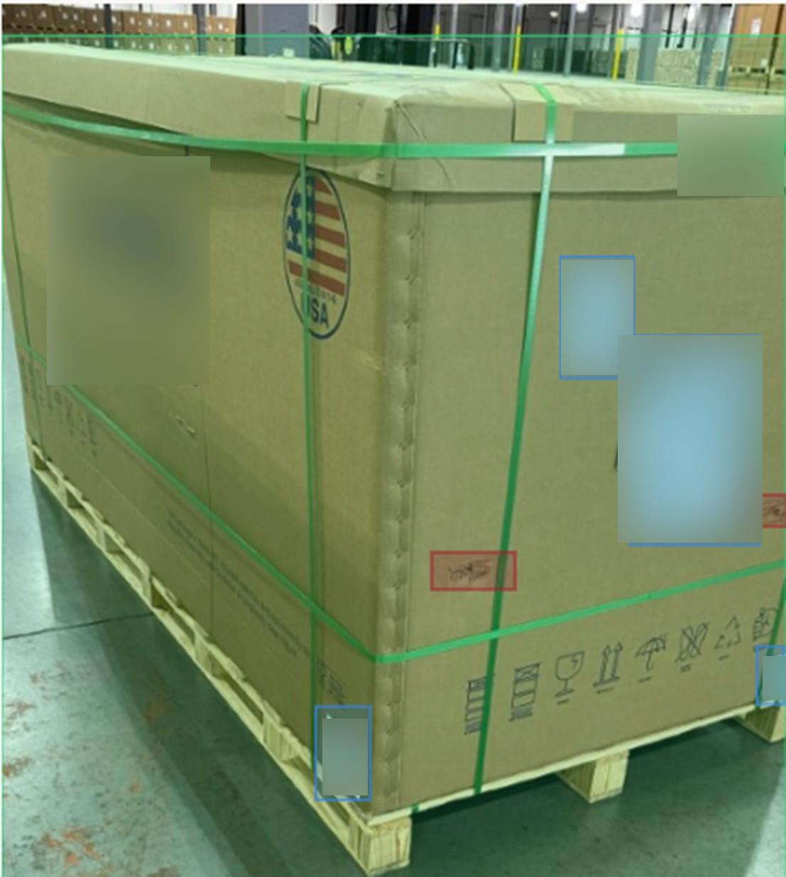
We’ve developed an automated pallet damage detection system that uses computer vision and machine learning to inspect pallets in real time as they enter through a dock door. The system captures live video, runs AI-based analysis, and flags damage as the pallet enters a facility. It then records these results into a tracking system, which can be accessed by warehouse managers.
Key Features
Real-Time Detection: Provides instant alerts for damaged pallets during intake.
AI Detection: As more samples of pallets arrive, the AI model gets better over time.
Seamless Integration: Designed to work with existing loading dock workflows.
Dashboard Interface: Allows warehouse managers to view historical data, detection logs, and trends over time.
Continuous Improvement: Our solution allows the AI component of our system to continuously get better with every new pallet we detect.
Automatically Detecting Damage on Shipping Pallets
Aashir Tuladhar1, Nicholas Hubbard1, and Andre Mossi1
Computer and Information Science
Impact
Reduced labor costs and inspection time
Improved safety and product integrity
Better supplier accountability with visual evidence
Reduced liability
Technology
Our model takes in thousands of sample images, which we label with boxes using Label Studio, and then train a new model from it using the Ultralytics YOLO platform.
A Multi-Camera vision system, powered by four Seeed Studio reCameras provide live video streaming and a trigger service that starts the damage detection process. The reCamera video is streamed and stored locally on a Seeed Studio reServer
Industrial (a customized NVIDIA Jetson Orin NX), where an NVIDIA DeepStream pipeline detects pallet damage in real time.
Detected frames are then uploaded to Azure Blob Storage, and attributes of each frame (like timestamp, detections, camera source, etc.) are stored in a TimescaleDB database.
A custom React-powered dashboard gives warehouse managers a searchable, time-stamped record of pallet inspections with images and metadata.
ABSTRACT
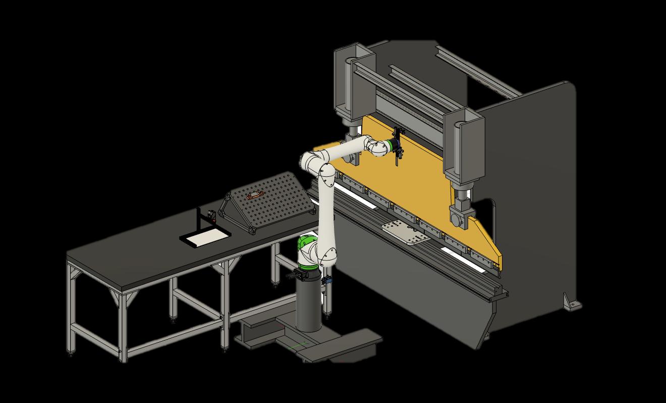
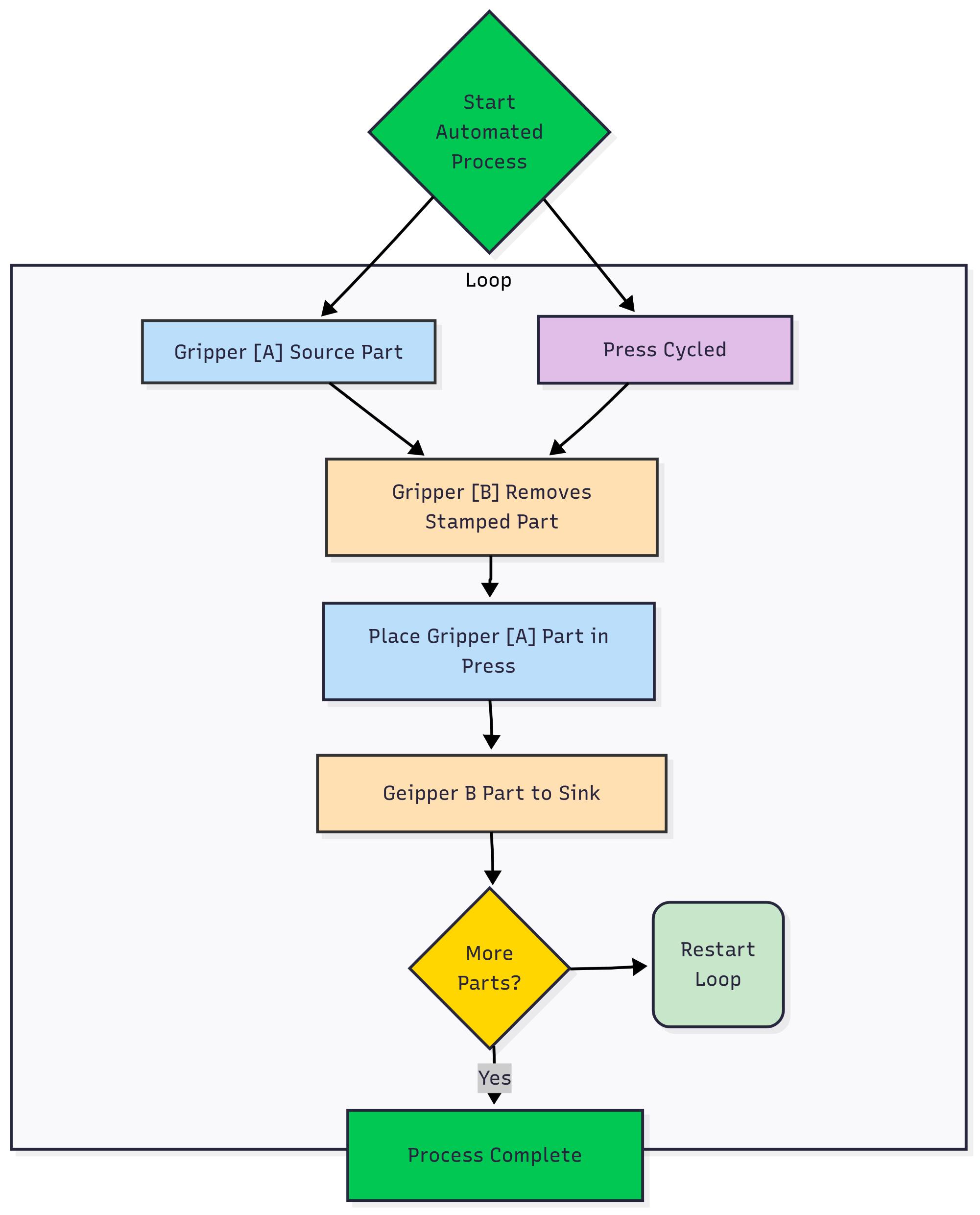
This project aims to develop an automated part marking system that utilizes metal stamps to accurately mark parts in a manufacturing environment The system incorporates a collaborate robot arm with vacuum grippers for part handling, a stamping mechanism capable of achieving the required 0 010-inch depth marking, and an Optical Character Recognition (OCR) verification system to ensure marking accuracy The automated solution addresses significant manufacturing challenges faced by ISM, including quality inconsistencies, efficiency bottlenecks, and customer satisfaction issues By implementing this system, the company expects to increase throughput, decrease defect rates, improve First Pass Yield, and reduce scrap and rework rates compared to the current manual method The project integrates precise positional tolerance, robust OCR validation with minimal error rates, and efficient stack load capabilities to optimize the manufacturing process This engineering solution demonstrates the practical application of automation technology to solve real-world manufacturing challenges while maintaining compliance with relevant international quality and safety standards
MANUFACTURING ENGINEERING
Process mapping was conducted to analyze the existing stamping workflow, identifying bottlenecks and inefficiencies This informed the cell layout redesign, optimizing material flow and operator movement Simulation tools were employed to validate proposed layout and automation changes before implementation, minimizing disruption to ongoing operations..
Quality management initiatives centered on the implementation of 2D vision automated verification of part markings However, a significant innovation was the creation of an in-machine fixture, ensuring consistent positioning during stamping operations This idea emerged from employee involvement, specifically an interview with a stamping operator who highlighted setup challenges and quality assurance delays
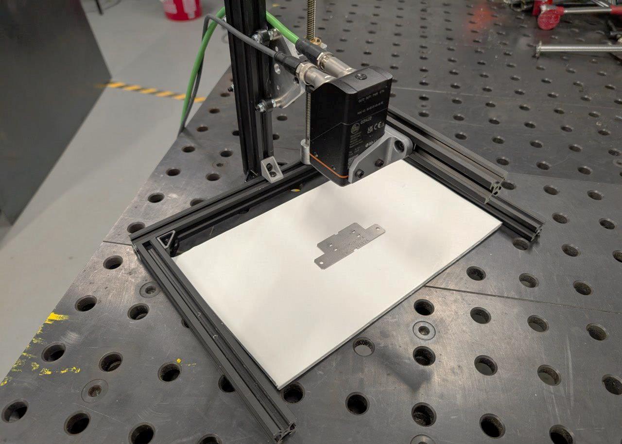
VISION OCR VERIFICATION STATION
The station is designed to handle verification in a portable and adjustable frame such that the plant can utilize verification beyond this automated cell The OCR algorithm accurately detects part numbers and reports them to a computer for verification The camera was specified to prioritize operations in adverse industrial environments and to analyze a range of parts This verification architecture enables automated quality assurance both within this cell and across the plant
END EFFECTOR
This vacuum end effector is designed to enable the robot to interact with the parts being stamped Low profile, inline, and high-vacuum venturi nozzles, paired with interchangeable cups, were utilized to meet lift requirements An appendage was added to fit within the 1/4” press-brake gap which was set to meet Osha Standards (1910 217) The 3 way 2 position valves were chosen with the added ability to operate in a plant environment subject to volatile pressure changes
ENGINEERED RESULTS AND DISCUSSION
This multifaceted solution reveals key insights about automation in job shop manufacturing environments
The manufacturing engineering improvements centered on fixture design, leveraging the standard ISM hole pattern to enhance cross-compatibility and facilitate rapid development of specialized attachments using offcuts or 3D printing. These improvements minimizes downtime to change between part SKUs
The Vision OCR verification system significantly improves quality assurance, eliminating incorrect or missing part numbers that can cause mass rework or scrap This automated solution outperforms manual inspection methods, effectively addressing quality concerns identified in operator/company interviews and assist in managing verification across part SKUs
The end effector design incorporates easily a dual suction cup configuration and interchangeable cups, accommodating diverse geometries while enabling simultaneous small part handling or increased lift for larger components This versatile approach optimizes changeover efficiency and operational range across part SKUs
Overall, the project demonstrates that strategic automation design focusing on flexibility can successfully address complex manufacturing challenges, enhancing quality and consistency even in high-mix, low-volume job shop manufacturing environments
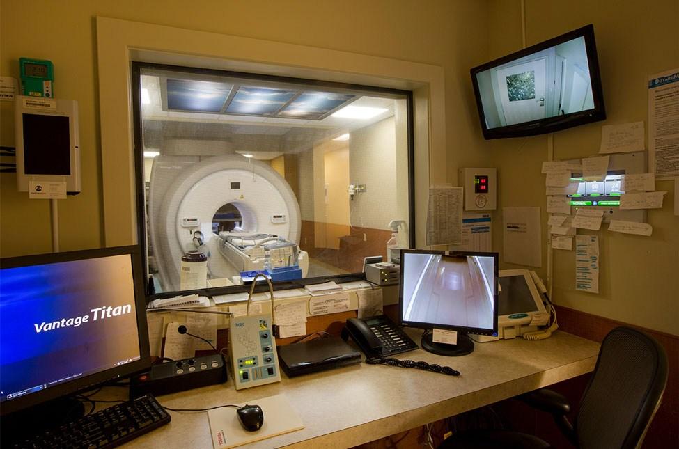
Modern MRI suites are designed with electromagnetic shielding that prevents any wireless communication, like Wi-Fi or Bluetooth, from working between the scan room and the control room. This shielding is essential for protecting patients and equipment, but it creates a major challenge for real-time interaction. While wired solutions are sometimes used, they are often bulky, inconvenient, and potentially hazardous in a clinical setting. Delays or miscommunications during scans can reduce workflow efficiency and affect patient care. Recognizing this gap, Bayer sponsored this project to develop a safe, lowcost, and scalable infrared (IR) communication system. By leveraging IR light, which can pass through the MRI room’s glass window, this solution aims to restore fast
and reliable messaging between technicians and operators without compromising patient safety or equipment integrity
Hardware and Software Design
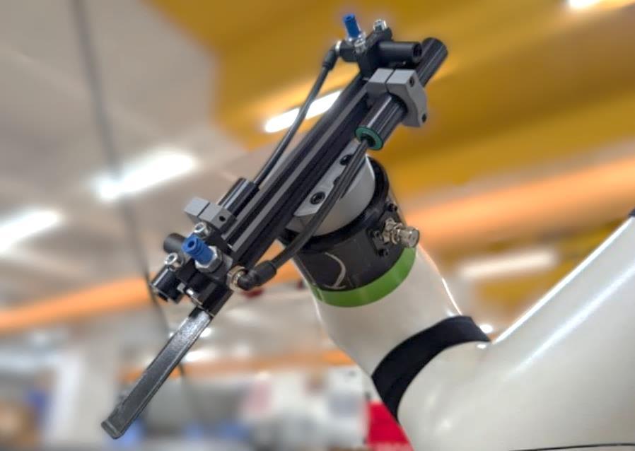
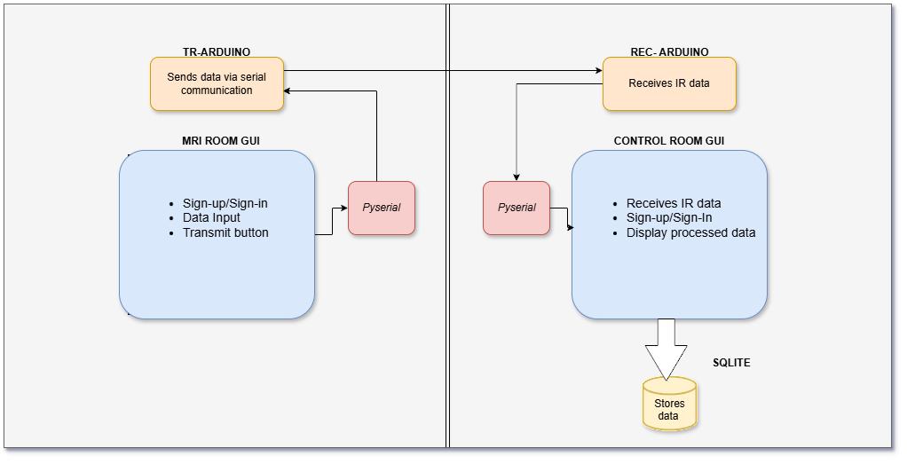
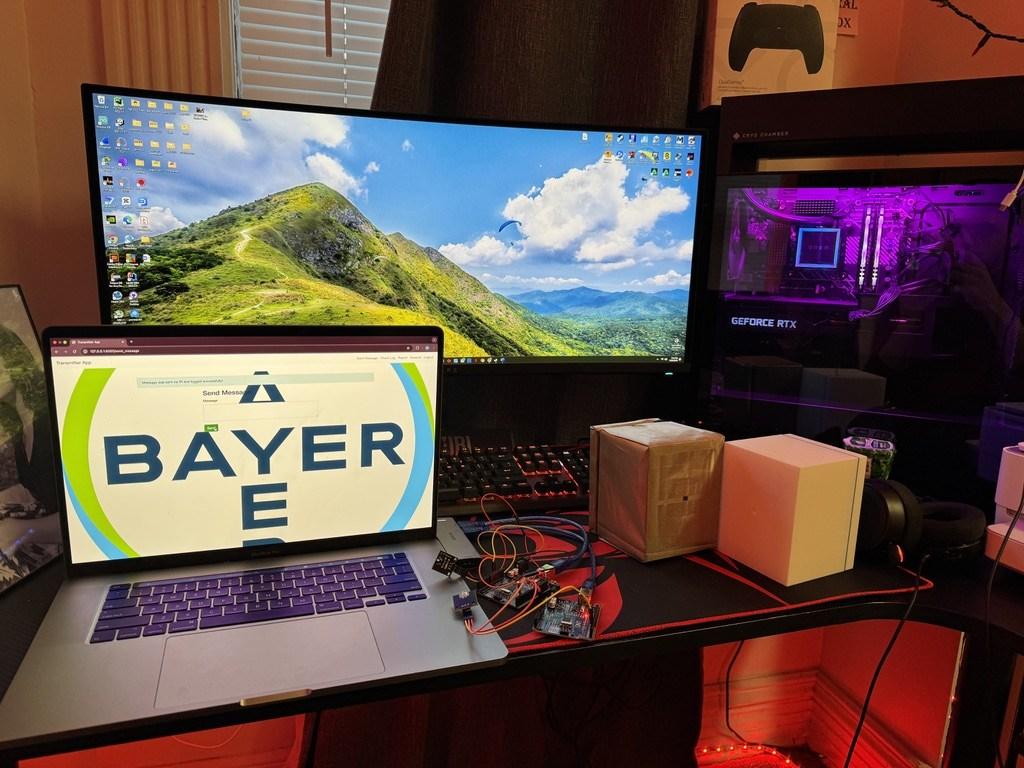
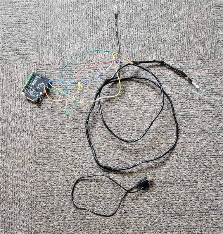
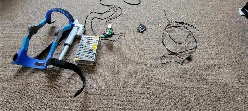
The system consists of two custom-built devices known as Pucks one placed inside the MRI scan room and the other in the control room. Each Puck is powered by an Arduino microcontroller and communicates using infrared (IR) signals. The MRI-side Puck contains an IR LED for transmitting messages and is enclosed in a Faraday cage to prevent electromagnetic interference with medical equipment. It operates on a rechargeable battery to eliminate the need for any physical wires that
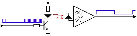
could pose risks during a scan. The control room Puck features an IR receiver and connects to a computer via USB. On the software side, Python-based transmitter and receiver applications are built using Flask and PySerial, enabling message encoding, streaming, and logging. Messages are broken into individual characters, each transmitted as an IR pulse with embedded error-handling logic . The receiver application processes these characters and displays them in real-time using Server-Sent Events (SSE) in the web interface. This architecture enables interference-free communication through the MRI room’s glass partition.
Results & Testing
Initial testing verified that the IR communication system could successfully transmit text messages through the MRI glass without signal loss or miscommunication. The Arduino-based transmitter and receiver worked with the receiver reconstructing messages accurately from
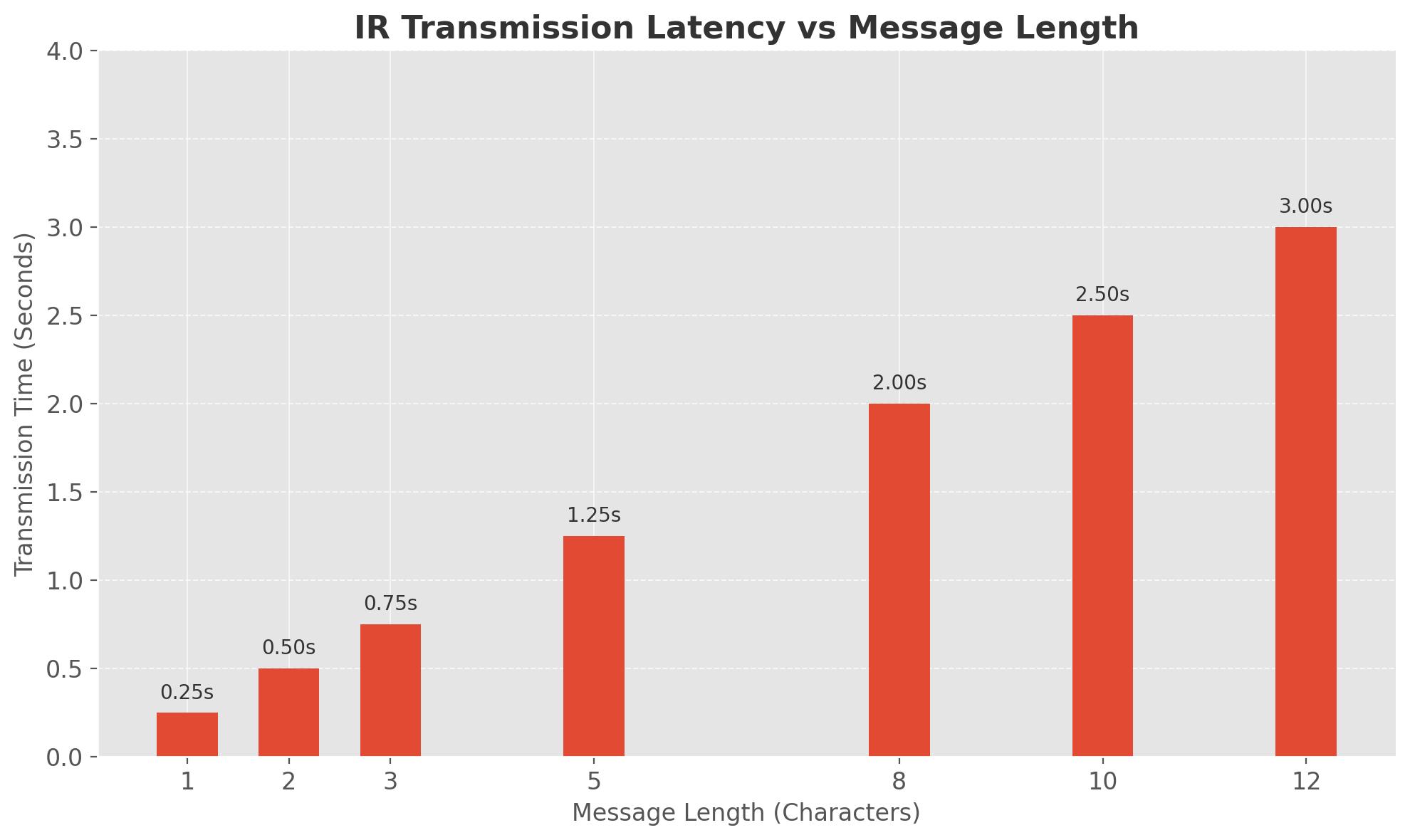
character-by-character pulses. Real-time updates were successfully streamed to the web interface via SSE, providing immediate feedback without requiring page refreshes. While the system proved fully functional, latency remained noticeable, particularly for longer messages, due to the timing constraints of IR pulse decoding. Nonetheless, the core objective of achieving wireless, interference-free communication within an MRI environment was met. Planned usability testing within an actual UPMC MRI suite will help assess real-world performance and operator feedback in a clinical context
Conclusion & Future Work
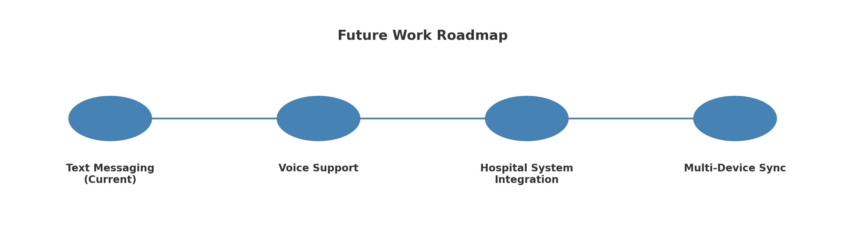
This project successfully demonstrates a practical solution for wireless communication in MRI environments using IR signals. The custom-designed Puck devices reliably transmit and receive data through the MRI room’s glass, avoiding electromagnetic interference and removing the need for unsafe cabling. Real-time message updates have been achieved through the integration of Flask and SSE. Future improvements include optimizing IR transmission speed to reduce latency, expanding the system to support predefined alerts or sensor feedback, and ultimately integrating voice communication. Long-term plans involve syncing the communication platform with hospital infrastructure such as electronic health records (EHR) and patient monitoring dashboards. With further development, this system can offer a scalable, production-ready tool that improves
workflow and patient safety in imaging facilities worldwide.
Figure 1: MRI Room View Through Shielded
Figure 3: Systems Architecture
Figure 4: Transmitter Setup with Puck Hardware
Figure 2: IR transmitter and Reception circuit
Figure 5: Transmitter App Message sent
Figure 6: Receiver App Message received
Chart 1: IR Latency Analysis – Message Length vs. Time
Figure 7: Future Work Roadmap
[ BraceX Rehabilitation Device ]
Abstract
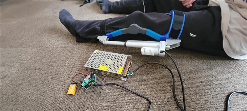
BraceX Rehabilitation is a device proposed to Gannon University students by Theralogics to enable patients to rehabilitate injured joints at home. By integrating a linear actuator, force sensors, and Bluetooth capabilities, the device bridges the gap between traditional physical therapy and digital recovery monitoring. The system consists of three main components: the Force Sensor System, the LinearActuator System, and a Mobile Application. The Linear Actuator System, connected to a 3D-printed brace, applies force to the patient’s limb, which must be resisted. Simultaneously, the Force Sensor System measures the force the patient exerts, offering valuable feedback on their progress.
Prior iterations of the project developed the Force Sensor and Linear Actuator Systems. This year, the focus shifted to incorporating Bluetooth technology for communication with a dedicated mobile application. Through this application, patients can track their applied force data, while clinicians can modify actuator speed based on real-time information. The application also streams data to a cloud database, allowing doctors to manage patient accounts. Physicians first set up patient profiles and calibrate device parameters through a secure login. Then, patients receive credentials to access their personalized application interface, enabling continuous progress monitoring and improved rehabilitation outcomes and continuous real-time feedback.
The BraceX app will display force values corresponding to users' movements. Users will have dedicated accounts, allowing them to securely log in and access their force data, which is stored in the database.
Image Top before force applied
Image bottom after force applied
There are two main hardware components of the prototype include:
1. The LinearActuator System (Figure ) – Control and power the linear actuator and applies force to the patient’s appendage. It is made up of a power converter, an Arduino, a ProgressiveAutomations PA14-4-150 linear actuator, and a 3D printed plastic brace. The power converter receives 120VAC from a wall outlet and converts it to DC power so it can be used by the other components of the system. TheArduino uses that power to control the linear actuator’s speed and stroke length. Each end of the actuator is attached to the brace on either side of the fulcrum.
The Force Sensor System (Figure Middle) – Gathers data from force sensors and transmits that data it to the application. This system is made up of anArduino Bluno and a pair of Flexiforce A301 force sensors. The force sensors are wedged between the patient and the brace. This allows the sensors to gather the force put on the brace by the patient against the actuator. The Arduino Bluno sends the data using a built in Bluetooth communication protocol.
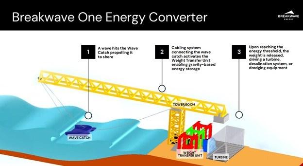
Breakwave Intermittent Energy Conversion
Abstract
This project explores the integration of Breakwave’s intermittent wave- energy conversion system into the coast of Lake Erie. The device from Breakwave energy utilizes a motorless wave catcher to capture intermittent energy from the waves and then converts its electrical power using a flywheel on shore. This system offers an eco-friendly alternative to traditional energy sources, reducing maintenance costs and environmental impacts while also eliminating the need for unsightly power lines in protected areas like Presque Isle. Key considerations for the project include durability, energy storage capacity, environmental impact, cost efficiency, and scalability. Design challenges involve adapting the system to Lake Erie's unique wave conditions and ensuring a stable power output through periods with lower wave activity. Various mechanical and electrical solutions, such as flywheels, alternators, and battery storage, are evaluated for optimal performance. The success of this project will likely lead to increased access to energy sources for energy scarce regions that have coastlines with untapped wave energy potential.
Project Objectives:
• Capture kinetic energy from waves
• Store energy using a flywheel mechanism
• Design a modular, low-maintenance system
• Improve consistency of intermittent energy input
• Evaluate performance under various wave conditions
Alternate Solutions:
Jacqueline Sandquist
Jacob Bacho
Performance Testing off the coast of California
Abstract
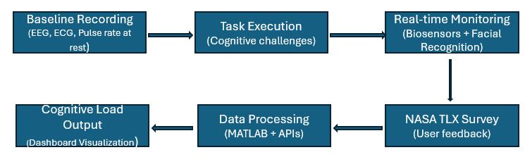
The Cognitive Load Measurement System is a multimodal tool designed to assess mental workload in real time using biosensing and behavioral data. This system integrates EEG, ECG, facial emotion recognition, and NASA-TLX to capture both objective and subjective indicators of cognitive fatigue. Through task-driven simulations, physiological signals are monitored and analyzed to produce a dynamic cognitive load score, helping users understand and manage their mental effort during high-demand tasks. With applications in education, healthcare, aerospace, and beyond, the system provides actionable insights via a real-time interface, supporting improved performance and wellbeing in cognitively intense environments
Scope & Goals
Problem: No accessible, real-time tracking system for cognitive load.
Goal: Multi-sensor solution (EEG, ECG -heart rate) with real-time visualization and alerts.
Boundaries: Currently tested in classrooms/labs, with potential to expand to clinical and industrial environments.
Security & Privacy: Ensure safe transmission and storage of user data.
Holistic Integration
• Multi-Sensor Data: Incorporates EEG, ECG, and heart rate measurements to capture objective physiological signals.
• Subjective Feedback: Integrates NASA-TLX surveys for user-reported cognitive load, adding valuable context to sensor data.
• Facial Emotion Analysis: Uses AI-driven webcam inputs to detect emotional states, further enhancing load measurement accuracy.
Comprehensive Real-Time Picture: Combines all inputs to offer richer insights than any single metric could provide.
Computer Science program and Biomedical Engineering program, Gannon University, Erie, PA
Methodology
Results / Observations
Results & Observations
• Classification Accuracy: Early tests show an 85–90% accuracy rate in distinguishing different cognitive load levels.
• Real-Time Latency: Data processing and visualization consistently maintain a 1.5–2 second delay from collection to dashboard display.
• User Feedback: Participants reported heightened awareness of their mental states, with NASA-TLX findings closely mirroring the system’s sensor-based scores.
• Practical Impact: Adjusting task difficulty in real time improved user engagement and prevented overload, while healthcare professionals noted the potential for stress monitoring during therapy sessions.
• System Reliability: Rigorous security measures and stable integration between sensors and the cloud backend minimized data loss and ensured continuous monitoring even in extended or high-load scenarios.
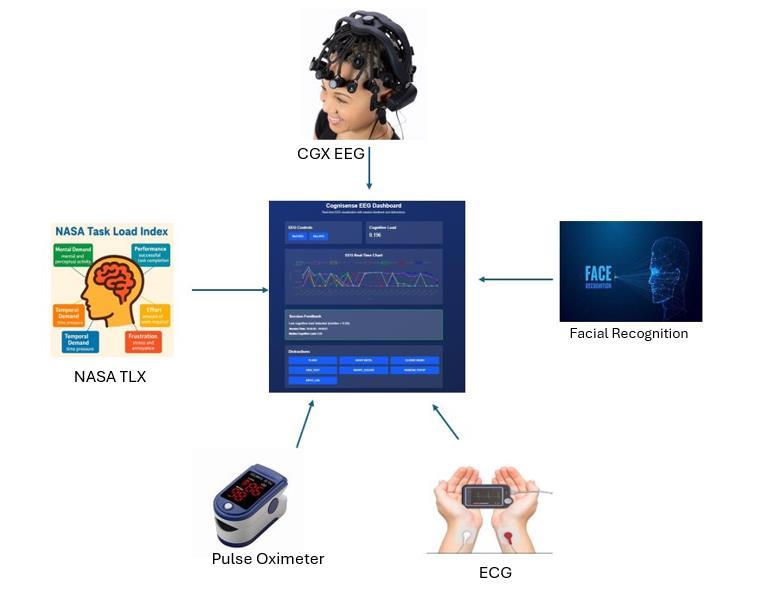
System Overview
★ Sensors & Data Collection
• EEG, ECG, Pulse rate
• Real-time streaming of physiological signals
★ Preprocessing
• Noise filtering
• Artifact removal
★ Feature Extraction
• Frequency analysis (e.g., EEG bands)
•Face recognition (fixations, saccades)
★ Machine Learning Analysis
• Classification or regression models
• Cognitive load estimation
★ User Feedback
• NASA-TLX survey
• Qualitative observations
★ Visualization & Output
• Real-time load monitoring dashboard
• Graphical or numerical summaries
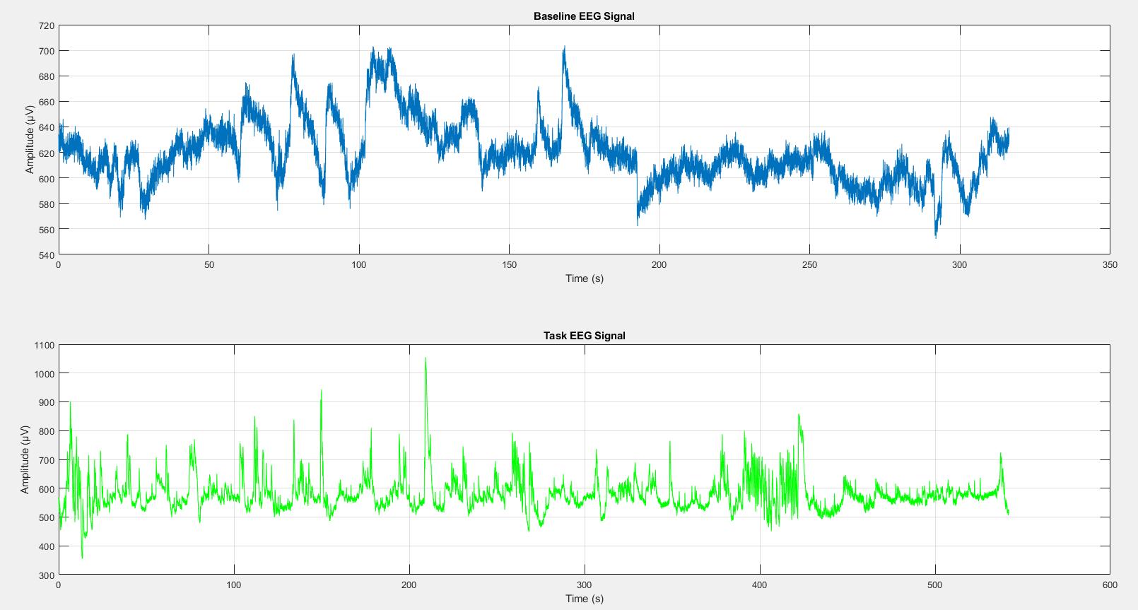
Fig 3. EEG Signal comparison
EEG amplitude during baseline remains stable (~560–700 μV), while task data shows higher peaks (up to ~1000 μV), indicating increased brain activity and cognitive load during task execution.
Future Potential
• Machine Learning Refinements: Continual updates to classification models will boost accuracy and versatility.
• Extended Use Cases: Applicable to diverse environments, from classrooms and healthcare facilities to aerospace operations.
• Infrastructure Upgrades: Improvements in hardware compatibility, backend efficiency, and user interface design will enhance real-time responsiveness.
• Security & Compliance: Strengthened protocols to protect sensitive user data, ensuring trust and reliability in high-stakes settings.
Fig 1. Methodology Overview
Fig 2. System overview Diagram
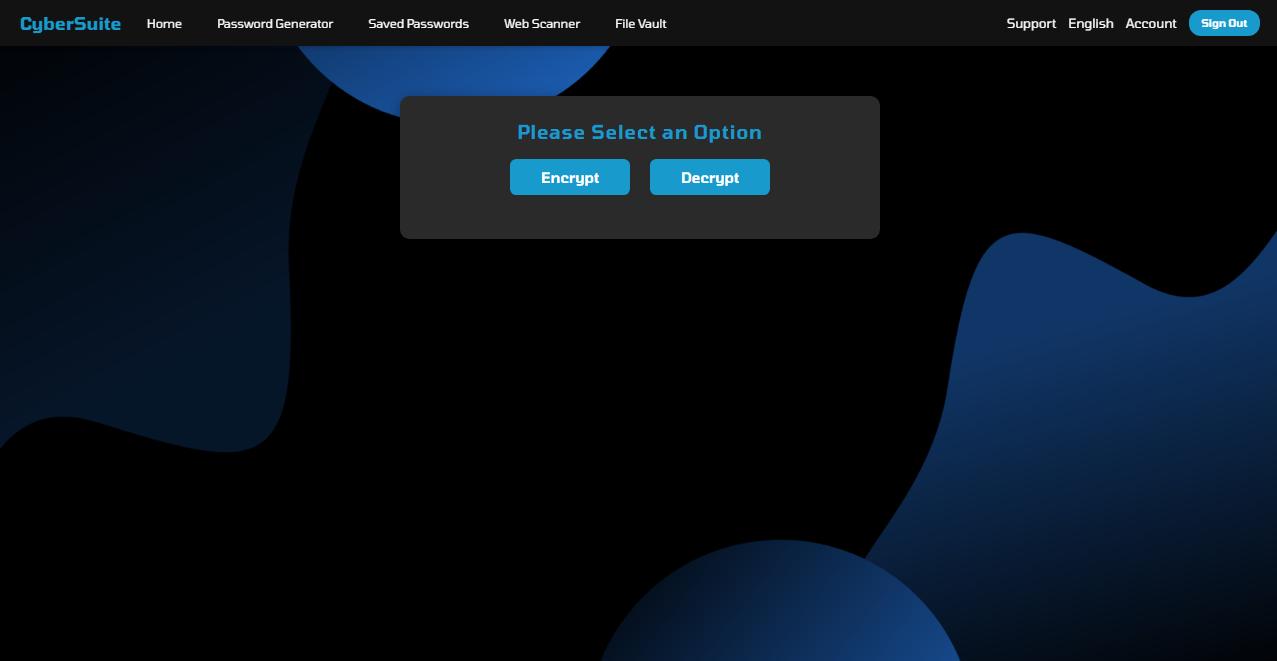
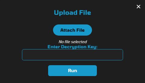
File Encryption
The CyberSuite File Encryption feature secures sensitive data by encrypting uploaded files withAES-256 encryption. Each encrypted file is paired with a unique decryption key, stored in a downloadable .txt file. This ensures that only authorized users with the correct key can decrypt and access the content, providing strong protection against unauthorized access
Key Features:
AES-256 Encryption: Encrypts files using the industrystandardAES-256 algorithm, ensuring robust data protection.
Unique Decryption Key: Generates a unique key for each encrypted file, saved in a .txt file for secure storage.
File Extension: Encrypted files are saved with a .enc extension to differentiate them from regular files.
Decryption Capability: Users can re-upload encrypted files and provide the correct key to decrypt and restore the original content.
Secure Download: Both the encrypted file and the decryp-
Cybersecurity Suite A Unified Security Solution
CyberSuite is a comprehensive cybersecurity solution designed to safeguard users from online threats through three core tools:
Security Scanner – Identifies website security flaws to prevent the average user from falling victim to phishing and smishing. Implemented using Laravel, we leverage its secure request handling, built-in authentication, andAPI integrations to ensure robust and reliable scanning while adhering to NIST Cybersecurity Framework (CSF) guidelines.
Password Generator & Storage – Asecure system for generating and managing strong passwords, utilizing encryption and hashing techniques to prevent unauthorized access. Built with Laravel’s encryption and hashing features, we ensure secure key storage.
File Encryption – Protects sensitive files by encrypting them with industry-standard algorithms. Laravel’s built-in encryption functions ensure secure and efficient file protection, preventing unauthorized access while maintaining usability.
Browser Extension Integration – For seamless user experience, CyberSuite can be implemented as a browser extension, allowing users to scan websites, generate passwords, and encrypt files from their browser without navigating to a separate platform. This ensures instant security at the click of a button while maintaining efficiency and ease of use.
Password Generator
The CyberSuite Password Generator provides a secure and efficient solution for creating strong passwords while prioritizing user convenience and data protection. The system uses user inputs such as a word, a number along with a secure UUID to generate unique and complex passwords.
Key features include:
Key Encryption: Passwords are never stored directly. Instead, we encrypt the generated keys and store only the encrypted versions in the database, ensuring that sensitive information remains protected against unauthorized access.
Easy Regeneration: Users can effortlessly regenerate their passwords using the stored encrypted keys, maintaining access while ensuring security. This approach enhances user experience by providing quick and convenient password management without compromising safety.
The CyberSuite Password Generation and Storage system exemplifies a balance between robust security measures and user convenience, enabling individuals to manage their passwords safely and efficiently.
The CyberSuite Scanner is a powerful tool designed to assess the security posture of websites by performing comprehensive scans for vulnerabilities such as open ports, vulnerable communication practices, configuration issues, and potential phishing threats. By leveraging advanced scanning techniques and real-time analysis, our scanner provides users with actionable insights to enhance their online safety and protect sensitive information. Its user-friendly interface and robust reporting features make it an invaluable asset for individuals and organizations alike, ensuring a safer web experience.
Key Features:
DomainAnalysis: Provides registrar name, creation date, and domain age for credibility assessment.
InputAnalysis: Detects SQL injection and Cross-Site Scripting (XSS) vulnerabilities.
Open Ports: Identifies potential vulnerabilities in open ports, including risky services i.e. RDP.
Protocols: Evaluates the security of TLS communication protocols.
Certification Info: Displays SSL certificate issuer and expiration date.
Cipher Strength:Assesses encryption strength to ensure data protection.
Scoring: Based on NIST guidelines that evaluates security vulnerabilities, providing users with a clear rating that indicates the overall safety of a website. Publications used to assess include: SP 800 40,41,52,57,177.
Andrew Nawrocki
CyberSuite
Web Scanner
Ridha Al-Quraishi
Abstract
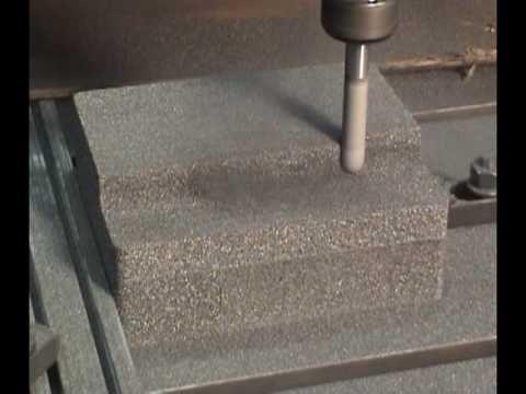
This project focuses on utilizing two materials; Brewer’s Spent Grain (BSG) and CFOAM as additives in concrete to improve construction materials and explore biomedical applications BSG has shown the potential to enhance concrete’s mechanical strength, water tightness, and irradiation resistance, and it may also improve bone cement biocompatibility, potentially benefiting orthopedic surgeries We are testing both materials in two concrete formulations, Dukelite Mix and Concrete Mix, at concentrations of 0 1%, 0 8%, and 5%, to evaluate its impact on properties like durability and sustainability In parallel, CFOAM, a carbon foam derived from coal waste, is utilized for stormwater treatment However, after discovering that CFOAM could leach heavy metals, we shifted our focus Rather than discarding CFOAM, we decided to incorporate it as a separate additive to concrete to be added in the same concentrations as the BSG This collaboration allows us to explore how CFOAM’s unique properties, such as improved thermal insulation and strength, could further enhance the performance and sustainability of concrete By combining BSG and CFOAM, our research will evaluate BSG and CFOAM’s impact on durability, reflectivity, and environmental sustainability, assessing its viability for large-scale production across medical and construction fields
Our history and relationships. CFOAM® Carbon Foam from CFOAM LLC. (n.d.). https://www.cfoam.com/about-us/
Chemical composition of Brewer’s spent grain (BSG) | download table. (n.d.). https://www.researchgate.net/figure/Chemical-composition-of-brewers-spent-grain-BSG_tbl1_309542845
Future applications for Brewers’ spent grain New Food Magazine. (2017, April 20). https://www.newfoodmagazine.com/article/269/future-applications-for-brewers-spent-grain/
Standard test methods for sampling and testing concrete masonry units and related units (n.d.). ASTM International.
Evaluating Brewer’s Spent Grain and CFOAM as Sustainable Additives for Enhanced Concrete
1* Environmental Eng. Department 2* Biomedical Eng. Department
Project Plan
Phase 1: Evaluation of CFOAM in a Stormwater Filtration Setting
o This is an EPA test method that can be used to estimate the adsorption-desorption potential of a contaminant/material This means that this test is used to determine the potential for the material to leach into groundwater
o This test is a chemical analysis used to determine whether there are hazardous elements present in a material
Results: From these tests it was determined that CFOAM could not be used for stormwater filtration
Phase 2: Planning and Calculations
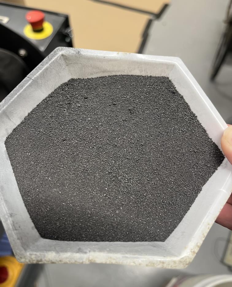
1. The percentage of additives (CFOAM and BSG) for each batch of concrete was determined
2. Using resources from A Duchini Inc , a concrete recipe was created that includes the following ingredients:
o BSG
o CFOAM
o Bulk Cement
o Asphalt Sand
o Cedarville (Limestone)
o Riverlite
3. A total of 14 batches were completed, with 3 molds being produced per batch Therefore, a total of 42 molds were produced for further testing
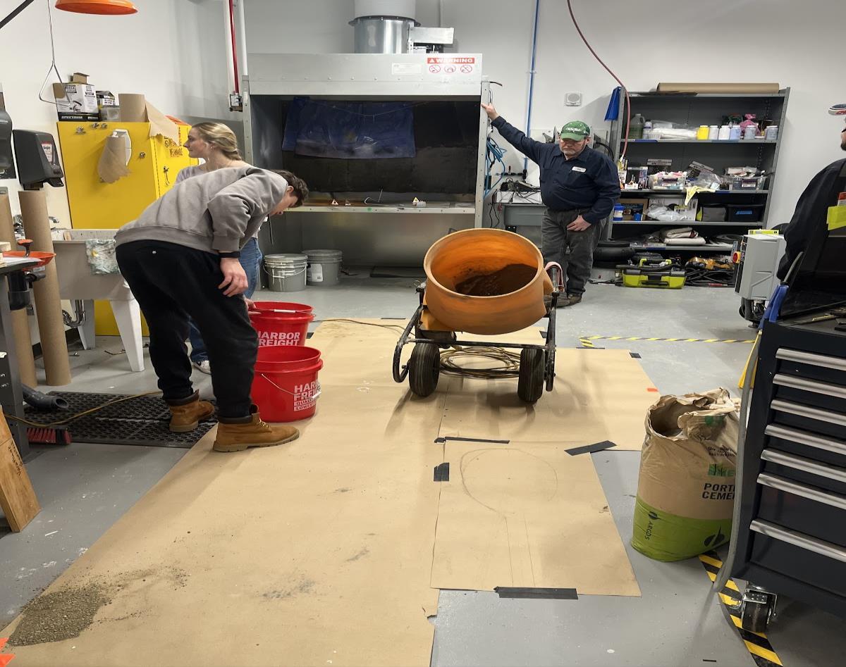
Phase 3:
1. Concrete Mixing
o Using
2. Mold Setting
o Must set with moisture, so each mold was placed in an incubator set at for at least 24 hours
Phase 4: Concrete Testing
1. Compression Testing
o Compressive strength tests are used to ensure that concrete masonry units meet the minimum strength requirements of the applicable unit specification. For compressive strength determination, three specimens are tested.
2. Fire Resistivity Testing
o Fire resistivity testing is used to ensure the material maintains its integrity in the event of a fire and meets the required intensity that is needed for its intended applications.
Elijah Cincinnati1
Anna Grychowski1
Elijah Ruppert1
Ella Seifert2
Peter Wagner2
Background
CFOAM is a carbon foam with excellent mechanical and thermal properties that is utilized as an alternative to conventional materials in thermal insulation, fireproofing, and composite tooling; among others. This foam "is designed to meet growing demand for ultra-high performance engineering materials in the military, industrial, aerospace, and commercial product markets."
The other additive we are exploring, BSG, is a byproduct of the brewing industry and consists of the leftover grains after brewing beer. This material is comprised of the fibrous remnants of barley malt as well as hemicellulose, cellulose, and protein. Currently, BSG is mainly used as animal feed with other applications as fertilizer and an energy source. A local masonry company, Duchini, is providing us with materials to test these additives in their two different formulations, Concrete and Dukelite. The company utilizes compression and vibration molding to formulate their blocks that are customizable based on the customer needs
eVTOL Vibration Isolator – Parker Lord Sponsored Department of Industrial Engineering
Andres Esteban, Chenay Date Line, and Dr Xiaoxu Ji, Gannon University, Erie, PA
Abstract Materials and Methods Results
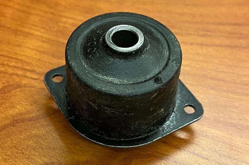
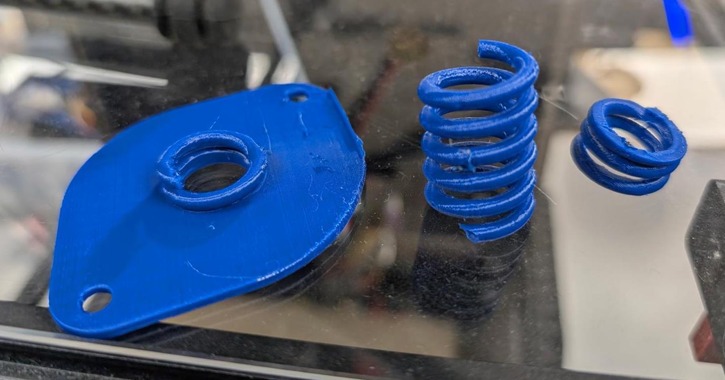
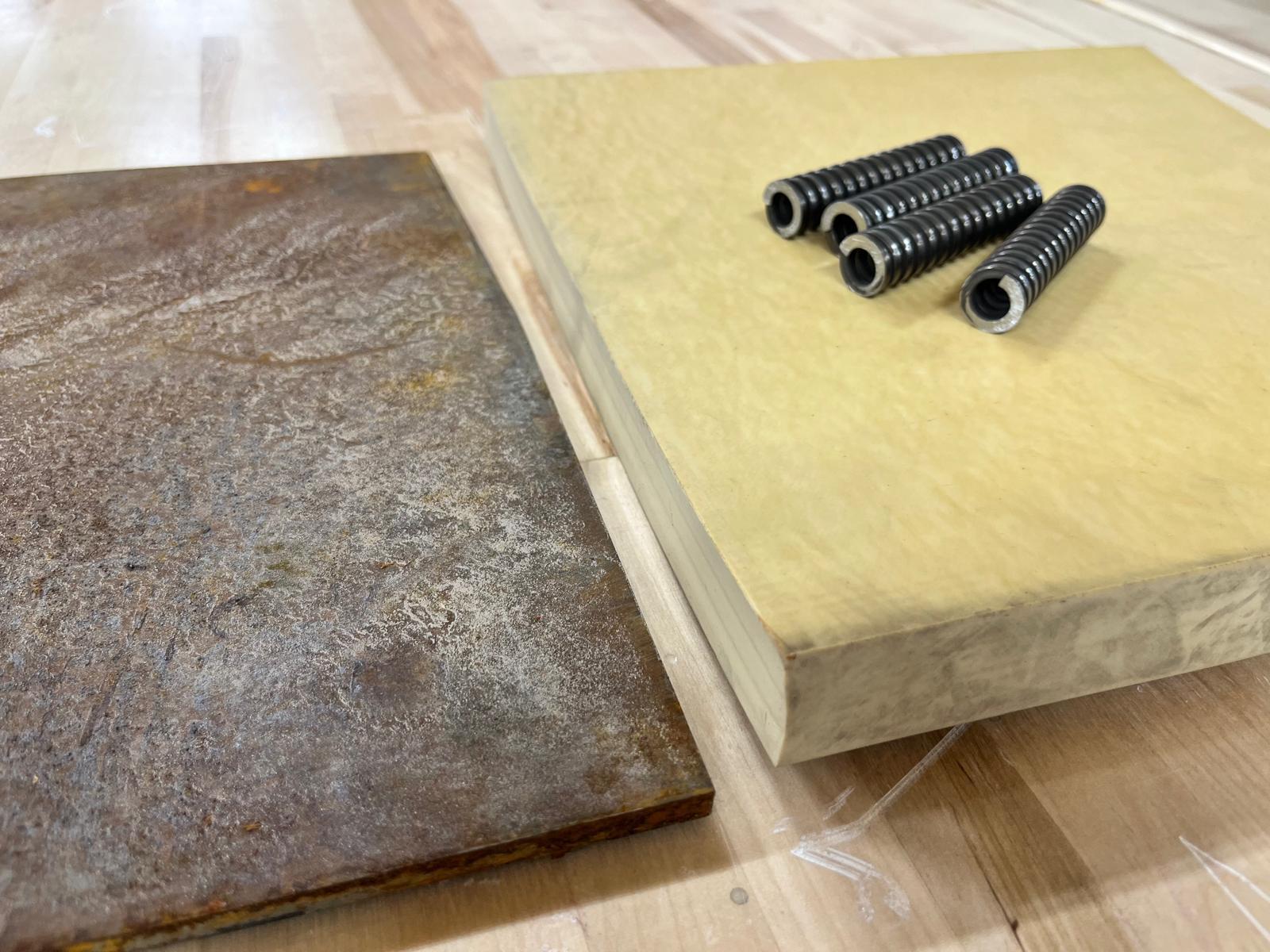
This study develops a vibration isolation solution for an Electric Vertical Take-off and Landing (eVTOL) system. The solution targets frequencies above 5Hz as they affect measurement accuracy, component durability, and pilot comfort. Our system combines an innovative metallic base, central spring and a rubber mount to minimize the vertical axial vibrations and withstand the stiffness and weight configurations. The selection of materials was decided through external research and testing to create an optimized isolator design that complies with various aviation standards. The vibration isolator system will help the company sponsor Parker-Lord by creating a cost-effective and lowmaintenance product that meets the industry demands for sustainable operations in the eVTOL industry.
Aim: To develop an innovative vibration isolation system for the eVTOL aircraft, focusing on frequencies above 5Hz, to enhance measurement accuracy, component durability, and pilot comfort while meeting aviation standards and industry demands for sustainable operations.
The design process involved multiple phases:
Material Selection: Literature review confirmed natural rubber as the ideal damping material. Stainless steel was selected for structural integrity.
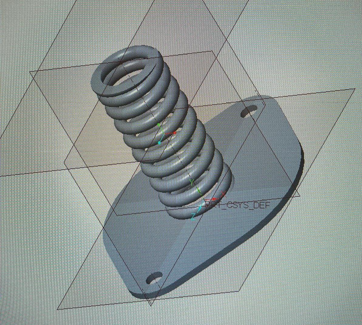
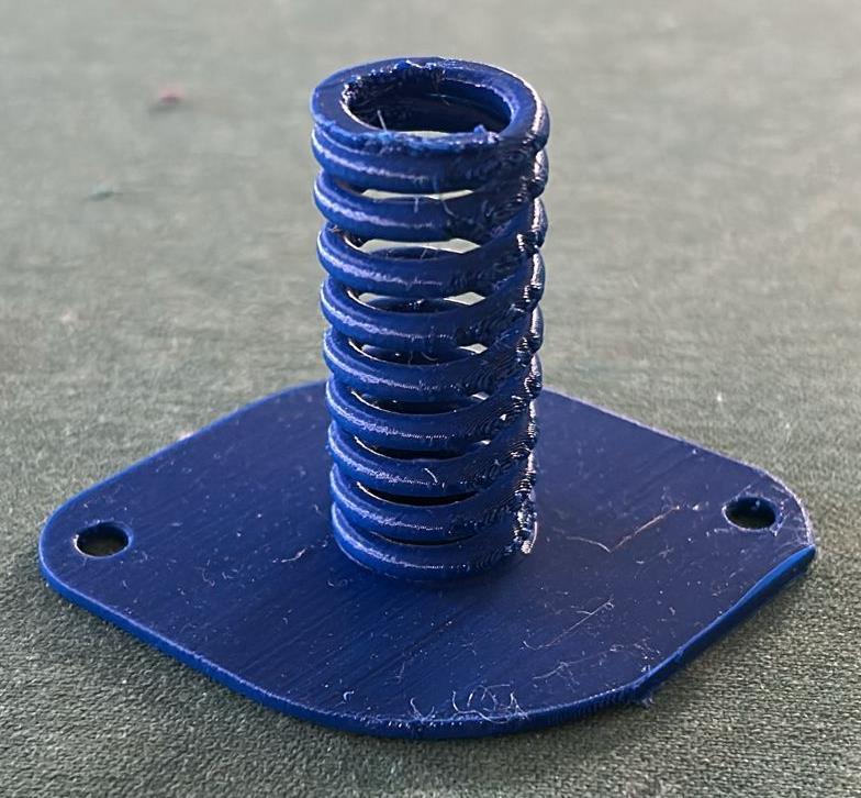
CAD Modeling: A base was modeled in CREO to accommodate rubber and spring components, ensuring compatibility with the eVTOL layout.
Component Sourcing: Springs and rubber sheets were selected from McMaster-Carr for practicality and affordability.
Procurement and Preparation: Components were ordered via Gannon’s Makerspace for assembly of four prototype isolators.
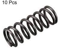
The spring has a height of 1.823 in, an outer diameter of 0.656 in, and an inner diameter of 0.406 in. From these measurements, the wire thickness was calculated to be 0.125 in, the mean coil diameter 0.531 in, and the total number of coils approximately 15.
Springs are notoriously hard to 3D Print. After many iterations, the decision to purchase the spring was chosen. Purchasing allows for superior mechanical properties, precision, and consistency which complies with aviation standards.
Discussion
The use of natural rubber and off the shelf springs offers a balance between performance, cost, and ease of assembly. The design avoids expensive manufacturing while meeting space and load requirements. Preliminary analysis suggests the isolator will reduce vibrations above 5Hz, improving comfort and system reliability in eVTOL applications.
This project introduces a practical and effective vibration control solution tailored to the needs of modern eVTOL systems. The use of commercial materials ensures affordability and replicability, while the custom base design provides the structural foundation for improved vibration damping.
Next steps include:
• Prototyping and physical testing of the isolators
• Measuring vibration reduction performance
• Iterating design based on test results
Future Work References
• A. Preumont, Vibration Control of Active Structures: An Introduction, 4th ed., Springer, 2018.
• N. S. Ferguson et al., “Dynamic Properties of Natural Rubber for Vibration Isolation,” Journal of Sound and Vibration, vol. 327, no. 1–2, 2009, pp. 1–10.
• L. Y. Tong et al., “Design of Vibration Isolators for Electric Aircraft,” Aerospace Science and Technology, vol. 98, 2020, 105646.
• McMaster-Carr Supply Company, www.mcmaster.com.
Figure 1: Parker-Lord Vibration Isolator Sample
Figure 3: Raw Materials
Figure 2: CREO Model and Part Used for Prototyping with the Iterations
Heat Exchange Design for eVinciTM – Westinghouse Sponsored
Ra ’ad Abu Karki, Ryan Barclay, Dr. Robert Michael, Dr. Hamid Torab
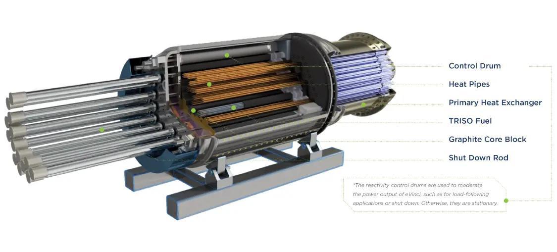
This project focuses on designing and testing a heat exchanger sleeve to efficiently transfer heat from a simulated nuclear heat pipe to a gas turbine engine while minimizing pressure drop. Unlike conventional designs, this approach utilizes parallel airflow to enhance efficiency. The design process involves CFD simulations to optimize fin geometry and physical prototyping. The experimental testing begins with cost-effective 3D-printed plastic models followed by a transition to a copper 3D-printed model for final evaluation. This research supports Westinghouse's development of the eVinci microreactor, contributing to cleaner and more sustainable energy solutions. By optimizing heat exchanger performance, this project advances Westinghouse's mission to resolve environmental and economic challenges associated with power generation in remote communities
Aim:
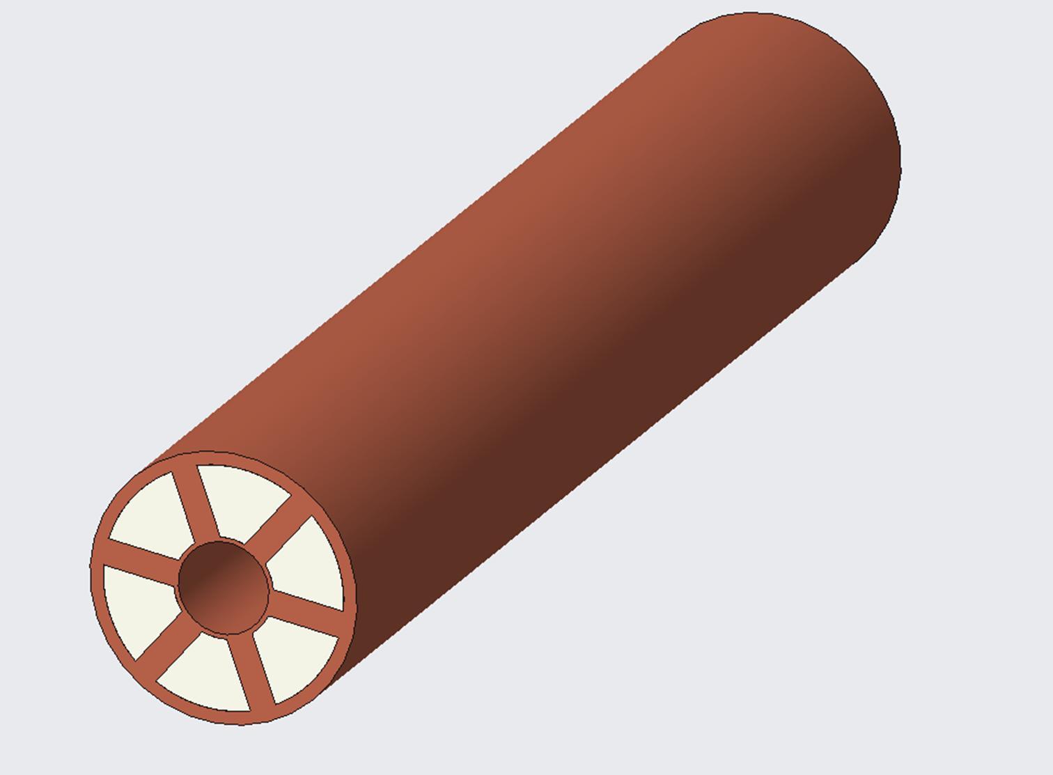
The challenge is to design an annular finned tube heat exchanger to maximize the outlet temperature while minimizing losses. The inner diameter, outer diameter, and length are constrained by the project guidelines, but the geometry and dimensions are subject to change.
Mechanical Engineering Program, Gannon University, Erie, PA Methods
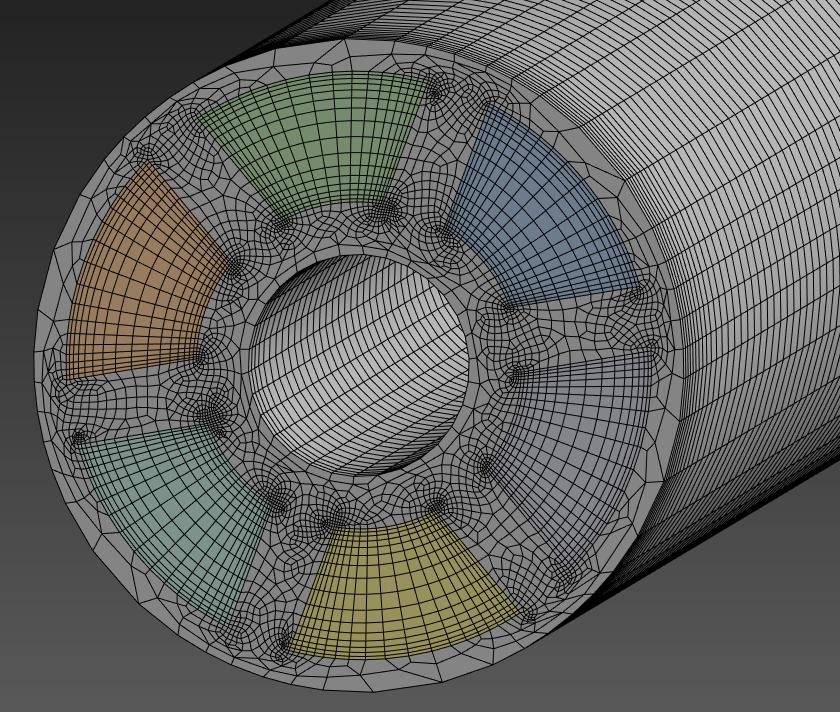
The original design was modeled in Creo Parametric 10.0 and analyzed in ANSYS Workbench. The geometry included six fins, 0.6 in long and 0.15 in thick. The pressure drop requirement limits the number of fins and their dimensions. The model described in Figure 2 is a benchmark that will be used to further optimize the design.
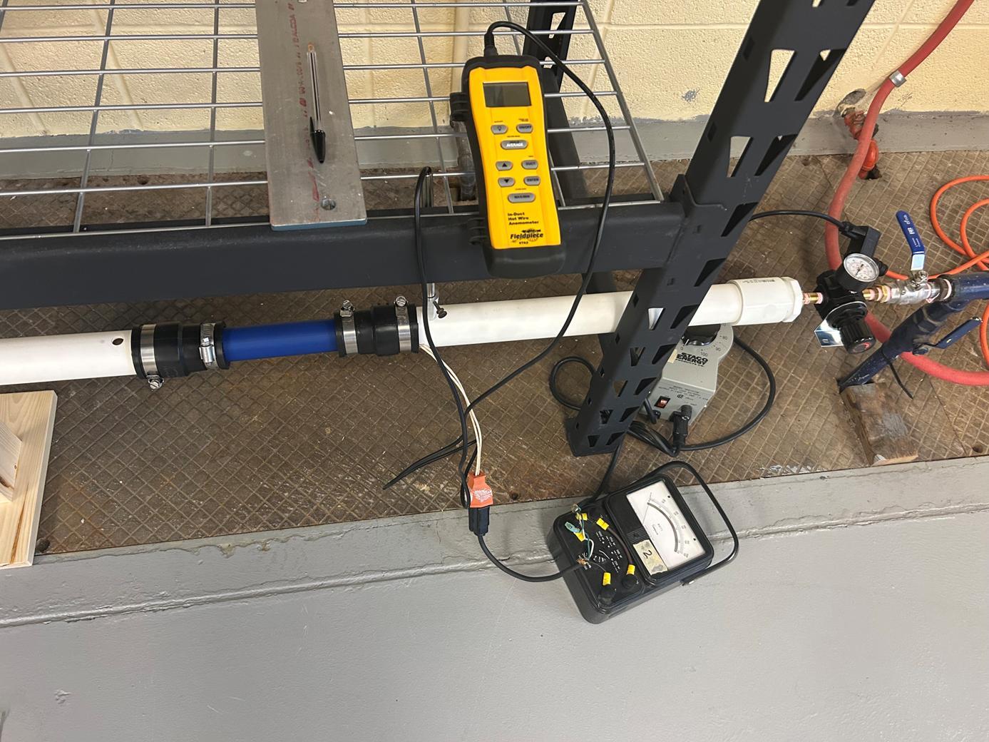
Figure 3 below describes the experimental validation rig for the project. The cartridge heater is a simulated nuclear heat source that transfers energy to the air. A PLAplastic model is tested to measure the velocity, the flow rate, and the pressure drop across the design. Experimental results verify the accuracy of the simulation data and suggest areas for design improvement. The final model will be 3D printed copper alloy to withstand the higher temperature conditions and maximize the heat transfer.
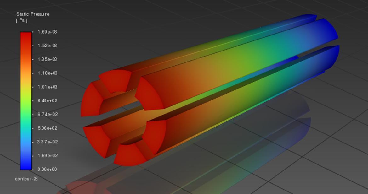
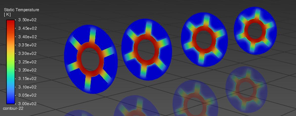
The performance of the heat exchanger sleeve was evaluated through CFD simulations and initial testing. The current design has a 0.5 in inner diameter, a 1.5 in outer diameter, and an 8 in length, as required by the project guidelines. The flow is turbulent, with the mass flow rate of air at approximately 0.04 kg/s. The pressure drop across the sleeve was measured, starting at 1.69 kPa (gauge) and exiting at 0 kPa. The total pressure drop of 1.69 kPa fulfills Westinghouse’s requirement of less than 2 kPa. Temperature analysis showed an increase in the working fluid’s temperature, starting at 27 °C and reaching 32.4 °C, for a temperature increase of 5.4 °C with the cartridge heater operating at 80 °C
Future
Work
• Verify the structural integrity of the sleeve using Finite Element Analysis
• Improve the accuracy of the simulation model by comparing to experimental results
• Optimize the design by analyzing the results with different geometries
References
[1] F. Careri, R. H. U. Khan, C. Todd, and M. M. Attallah, “Additive manufacturing of heat exchangers in aerospace applications: a review,” Applied Thermal Engineering, vol. 235, p. 121387, Nov. 2023, doi: 10.1016/j.applthermaleng.2023.121387.
[2] J.-C. Han, “Recent Studies in Turbine Blade Cooling,” International Journal of Rotating Machinery, vol. 10, Nov. 2004, doi: 10.1155/S1023621X04000442.
[3] R. Hernandez, M. Todosow, and N. R. Brown, “Micro heat pipe nuclear reactor concepts: Analysis of fuel cycle performance and environmental impacts,” Annals of Nuclear Energy, vol. 126, pp. 419–426, Apr. 2019, doi: 10.1016/j.anucene.2018.11.050.
[4] H. Jouhara, A. Chauhan, T. Nannou, S. Almahmoud, B. Delpech, and L. C. Wrobel, “Heat pipe based systems - Advances and applications,” Energy, vol. 128, pp. 729–754, Jun. 2017, doi: 10.1016/j.energy.2017.04.028.
[5] J. Li, J. Cai, and X. Li, “Conceptual design and feasibility analysis of a megawatt level low enriched uranium heat pipe cooled reactor core,” Annals of Nuclear Energy, vol. 181, p. 109576, Feb. 2023, doi: 10.1016/j.anucene.2022.109576.
[6] J. W. Sterbentz et al., “Special Purpose Nuclear Reactor (5 MW) for Reliable Power at Remote Sites Assessment Report,” INL/EXT--16-40741, 1410224, Apr. 2017. doi: 10.2172/1410224.
Figure 1. Schematic of eVinciTM Microreactor
Figure 2. Heat Exchanger Design
Figure 3. Experimental Validation Rig
Figure 5. Pressure Contour
Figure 6. Temperature Contour
Figure 4. Mesh
High Gauss Field Test Fixture
Project Description:
MR scanners contain 0.5 - 7 Tesla magnets to provide a strong, uniform magnetic field Electro-Mechanical components that utilize magnetic fields (e.g., ferromagnetic core inductors and DC motors) present challenges in the MR environment, so PCBs and motors used in the MR Suite must be specially designed to be "MR Conditional." The goal of this project is to create a text fixture that generates a high gauss field (at least 5,000 gauss, or 0.5 Tesla) and is large enough to place PCBs and/or motors within to test their functionality under simulated MR magnetic field conditions.
Inspiration for the Project:
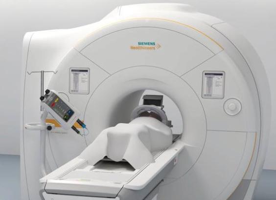
Injectors are used with MRI machines to highlight certain tissues for imaging. These injectors are incredibly useful for generating clear images with the MRI, however, the issue with them is that they are attached to the MRI (see Figure 1) and are very close to the magnets while the machine is running These injectors contain ferromagnetic materials, which affects the magnetic field generated by the machine and the injectors can be damaged themselves Therefore, Bayer is in search of a way to test the components of the injectors to ensure that the parts being installed into the injectors are safe.
Our Plan:
As stated in the project description, Bayer is in search of a way to test the MR conditionality of the components in the injectors before they are installed in the MRI equipment. Our plan is to use Creo and ANSYS Magnetostatic simulations to design a solenoid coil and a magnetic circuit that can generate a magnetic field to mimic that of an MRI machine to ensure that the components being installed are MR conditional.
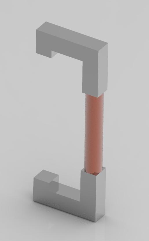
CAD Model:
Middle copper section: wires carrying electric current to generate magnetic field
Soft iron core: covered in copper wire; enhances magnetic field strength
Top and bottom brackets: steel brackets to guide magnetic field lines through open section of model
Future Design Plans:
▪ Simulate design usingAnsys or equivalent software
▪ Mechanism to hold PCBs while running tests
hansotte001@gannon.edu
schneide030@gannon.edu
ji001@gannon.edu
Anticipated Results:
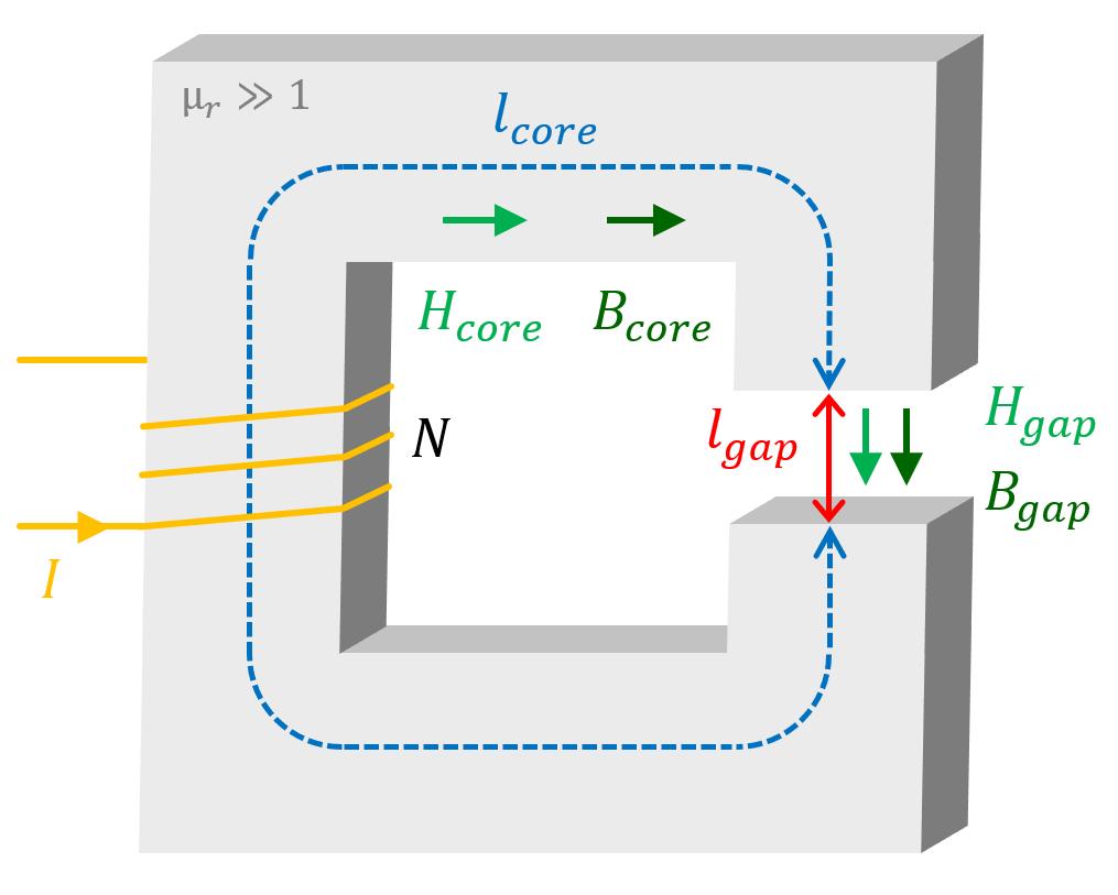
To properly analyze this system in ANSYS or another software, it is important to do hand calculations to find the boundary conditions that we will use in the simulation. We used the following equation to solve for the number of turns that we would need for our solenoid coil
B = Magnetic Field Strength (T)
L = Length of Solenoid Coils (m)
D = Inner Diameter of Solenoid (m)
μ = Relative Permeability of Core Material
I = Electric Current (A)
N = Number of Coil Turns
References:
[1] BayerAG. (2020, July 15). Bayer and Siemens Healthineers Present First Synchronized Imaging System interface for MRI. Siemens Healthineers https://www.siemenshealthineers.com/press/releases/isimricoupl ing.html
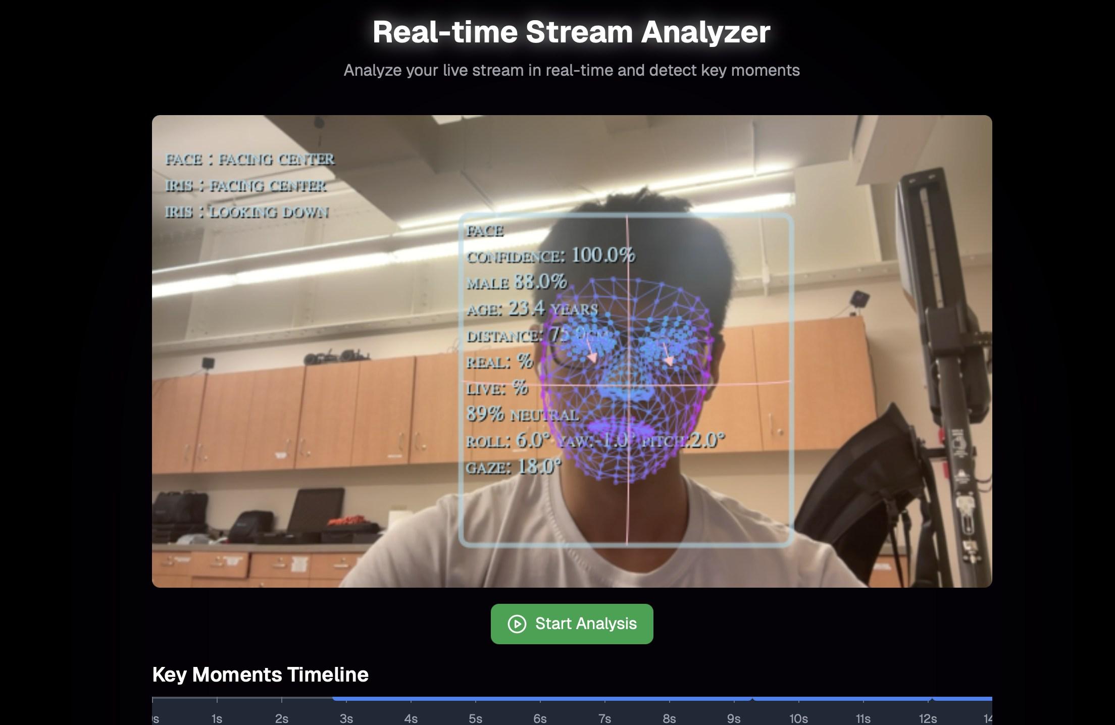
Abstract: Interview Grader is a system real-time evaluation system designed to assist recruiters and hiring managers in assessing candidates during interviews. Leveraging computer vision techniques, the system analyzes real-time non-verbal behaviors such as facial expressions, gaze detection, age detection, and body posture to provide objective, data-driven feedback. By integrating pose estimation and emotion recognition models, Interview Grader offers a consistent and unbiased assessment of a candidate’s engagement, confidence, and communication style. This tool aims to enhance the hiring process by reducing human bias, promoting fair evaluation, and enabling more informed decision-making
Technologies Overview:
Frontend: Next.Js/ ShadcnUI
Backend: NextJs, Supabase, Python
Framework: Pytorch, Tensorflow, Mediapipe.
Database: S3, InfluxDB,
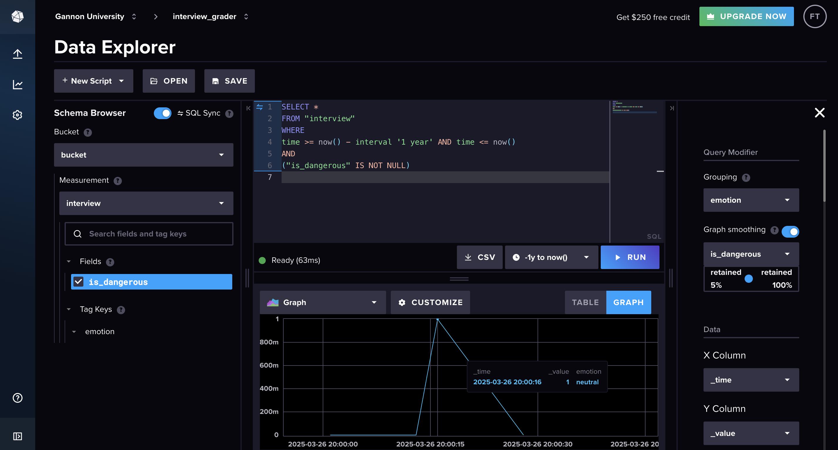
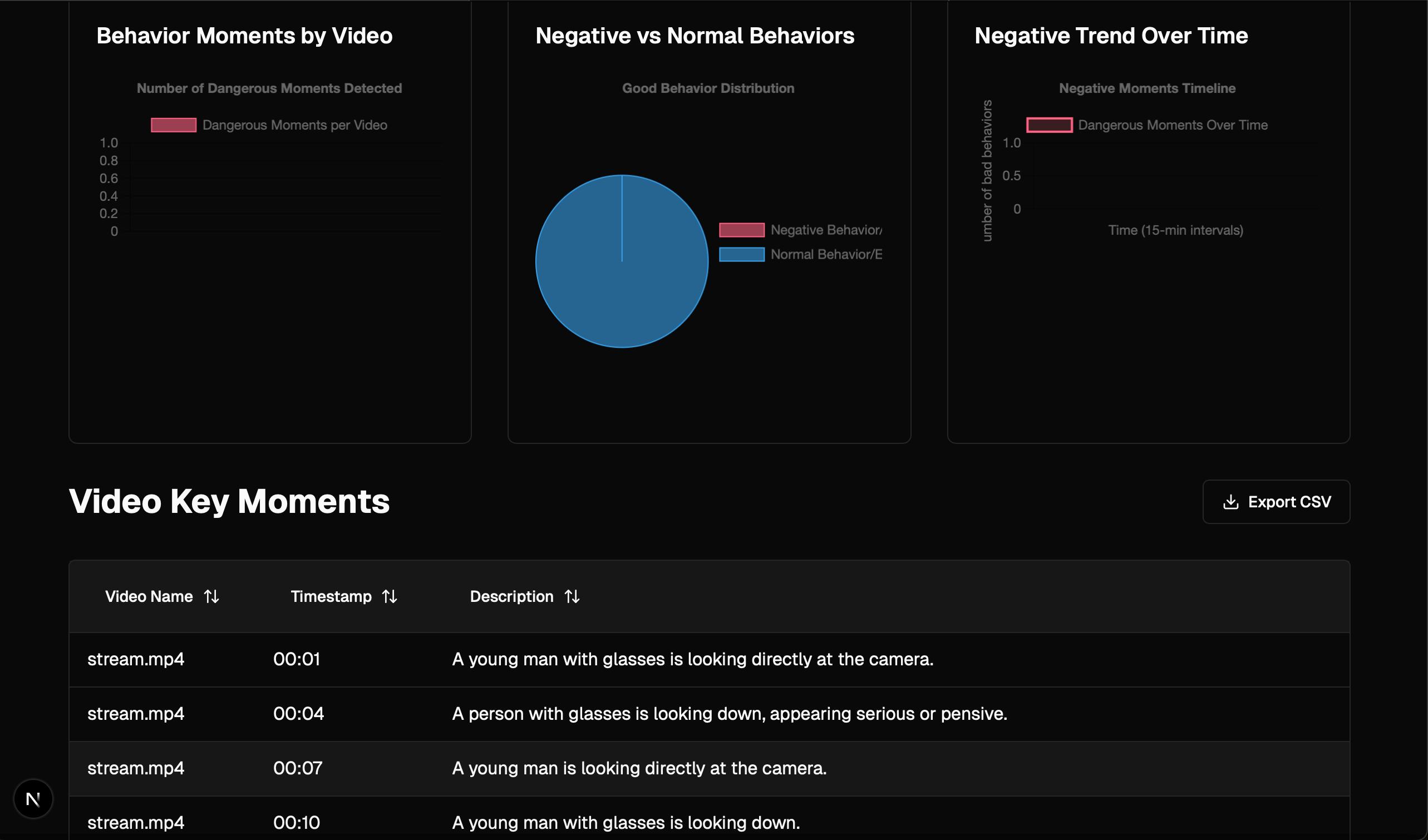
In our system, we leverage InfluxDB to store and visualize detailed interview grader report data. The pro-
cess begins by importing the CSV data generated by the interview grader model this file contains persecond timestamps, emotion scores, and flagging indicators. Once the data is in InfluxDB, we construct a dynamic dashboard that lets us track every second of the interview. This powerful visualization tool not only displays precise timestamps, but also highlights moments when significant emotions are detected and
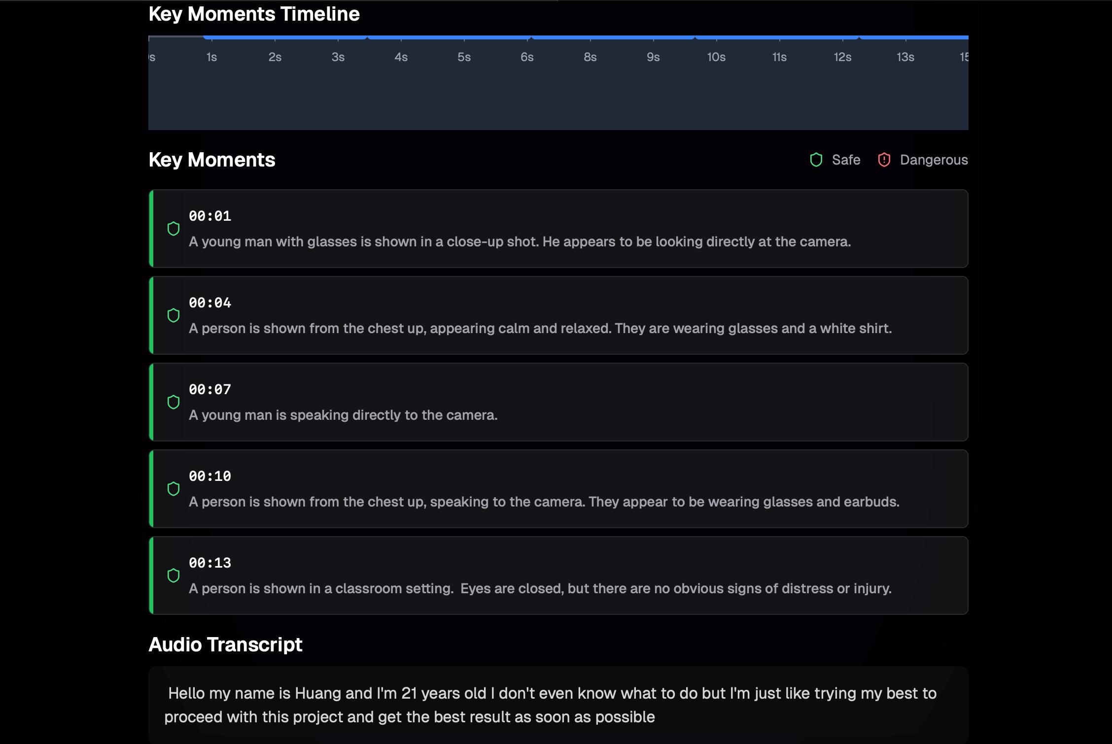
Real-time emotion detection, gaze detection, age detection, facial landmark detection, iris detection and posture detection during the interview, which helps recruiters capture all the macro and micro expressions.
Summarize both positive and negative moments over time and visualize them using intuitive graphs. These graphs provide a clear view of emotional shifts and key moments, helping to track sentiment trends and highlight significant changes throughout the interview. This makes it easier to identify patterns and assess overall performance.
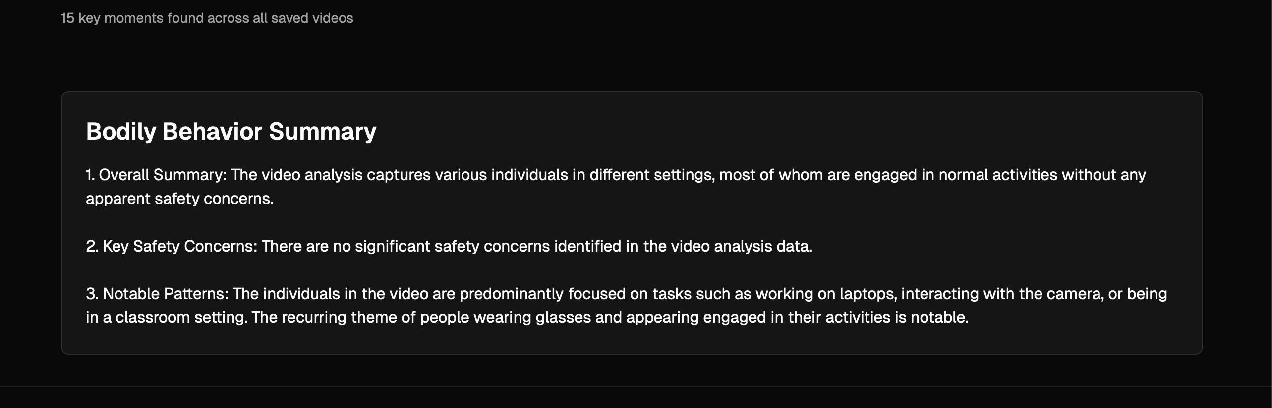
Multi-modal Vision Language Model. This technique is use to capture and contextualize image to text specifically for body language, enriched the data in order to help recruiters gets the overview of a candidate’s behaviors.
Summarize the candidate's body language to gain insights into their demeanor, communication style, and overall presence, which can help assess how well they align with the company’s culture and values. This analysis provides a deeper understanding of whether the candidate's behaviors and attitudes would make them a good cultural fit within the team and organization, contributing to long-term success and collaboration.
dang004@gannon.edu
tarhirli001@gannon.edu
uprety003@gannon.edu
Methodology: We use emotion detection powered by the Oarriaga Emotion model, which is based on a Convolutional Neural Network (CNN) architecture. The model processes 64x64 pixel images and employs several layers, including convolutional, pooling, and fully connected layers, to extract and classify emotional states. For body pose detection, we leverage MoveNet, a lightweight and fast model optimized for single-person pose estimation, processing images at 192x192 resolution. Additionally, face detection is handled by the MediaPipe BlazeFace model, which utilizes a lightweight CNN for real-time face detection, achieving high accuracy with 128x128 pixel inputs. All models are optimized with preprocessing, custom caching, and output normalization techniques to ensure efficient performance.
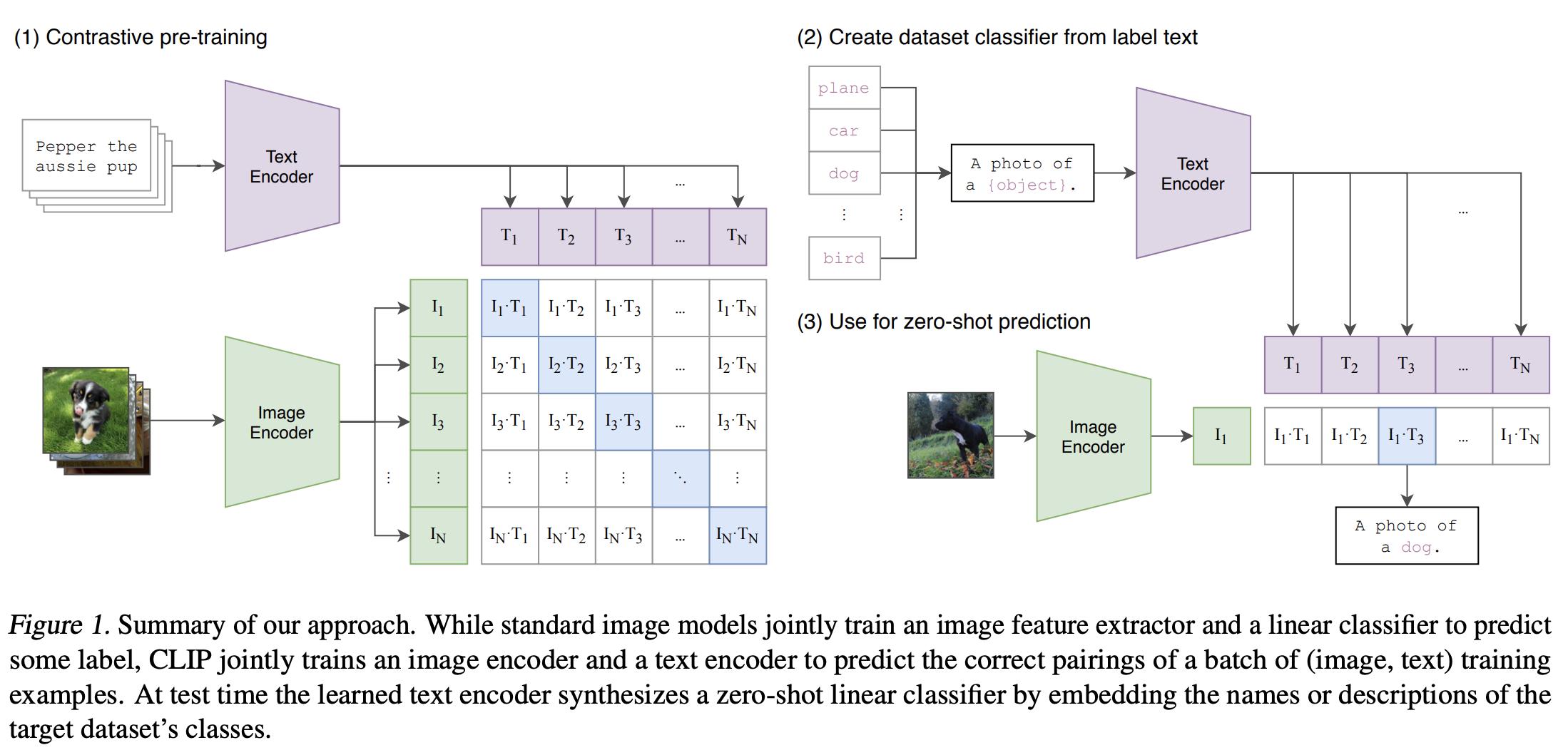
Vision Language Model: Contrastive Language-Image Pretraining (CLIP), consisting of a simplified version of ConVIRT trained from scratch, is an efficient method of image representation learning from natural language supervision. , CLIP jointly trains an image encoder and a text encoder to predict the correct pairings of a batch of (image, text) training examples. At test time the learned text encoder synthesizes a zero-shot linear classifier by embedding the names or descriptions of the target dataset’s classes. After that, we fine-tune the model using Low-rank adaptive method for faster inference.
Citations
1. Oarriaga Emotion Model: The emotion detection model is based on the work by Oarriaga et al. (2018), who proposed a CNN architecture for emotion recognition in the wild.
2. MoveNet: Pose detection utilizes MoveNet, a lightweight model for single-person pose estimation, as detailed by Google Research (2021).
3. MediaPipe BlazeFace Face detection is performed
Material and Design Optimization of Medical Seals for Steam Sterilizers
Introduction
Critical and semi-critical reusable medical devices are routinely sterilized using pressurized saturated steam in an airtight chamber, as required by law [1]. At a typical hospital, these steam sterilizers are shut off for only 14% of the calendar year [2]. Bacteria, viruses, fungi and spores can cause healthcare-acquired infections (HAIs) in patients which were “not present or incubating at the time of admission” [3]. 10% of patients in developing and 7% in developed countries on average, at any given time, will acquire a HAI [4]. Steam sterilizers are crucial for minimizing HAIs, but high-level disinfection relies on the gaskets ability to seal by generating high contact pressure against the sterilizer door.
An elastomer seals manufacturer is sponsoring a senior project to investigate alternative materials used in sealing applications for medical devices. The new compound formulation will be PFAS compliant while offering performance improvement, including reduced stick at the interface and increased durability. 25 candidate materials will be evaluated for properties such as tensile strength, compression set, abrasive wear, and friction. ASTM testing standards are consolidated to collect data and compare new elastomer formulations. Materials will be steam aged up to 6400 hrs using a steam flush pressure pulsing process to determine its effects.
Materials and Methods
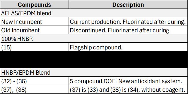
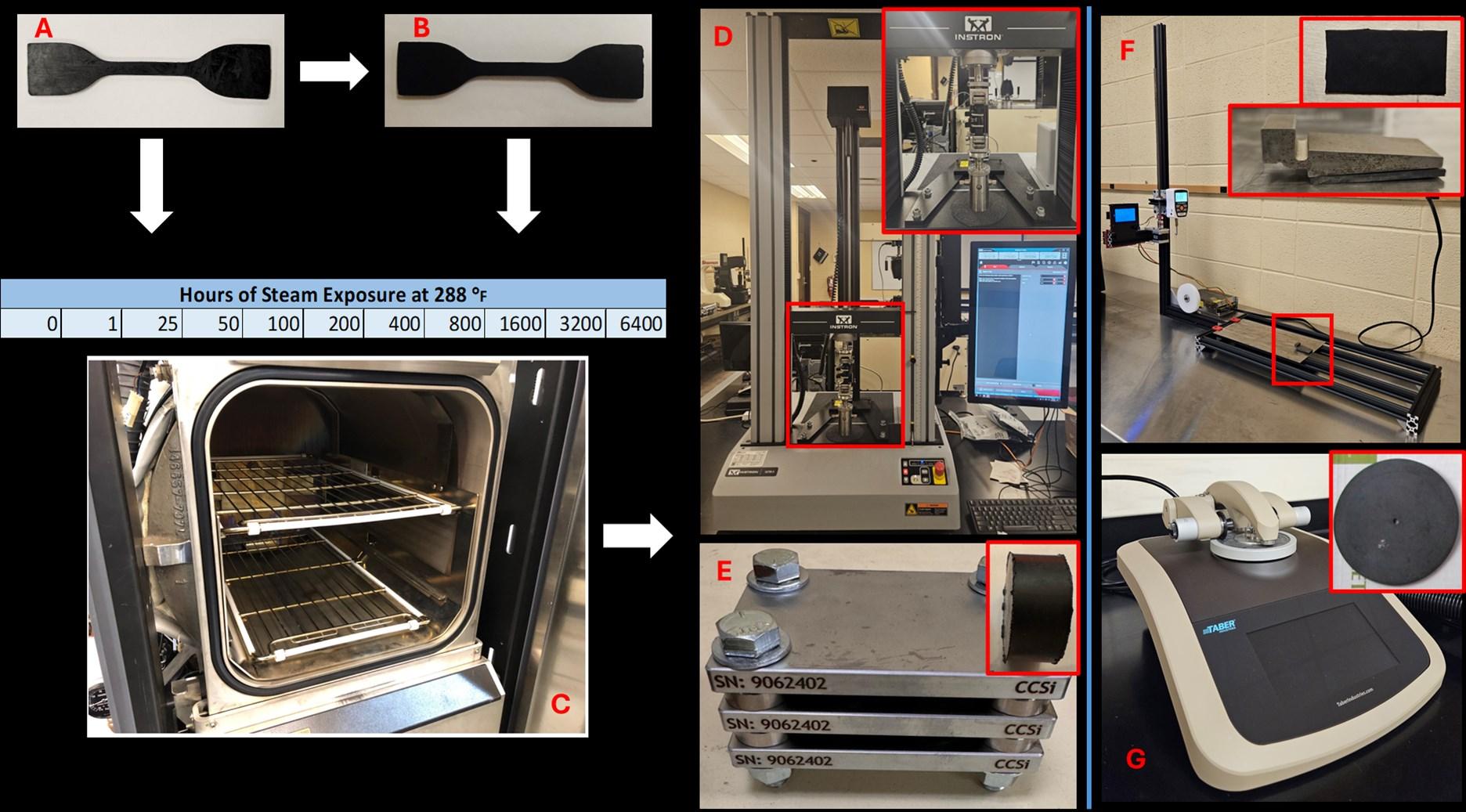
The families listed in Table 1 are chosen and provided by the manufacturer. The parenthetical numbers identify the compounds, each having different elastomer blends and additives. Many compounds are in a design of experiments (DOE) group of 5. All contain carbon black, vulcanizing agents, and antioxidants, etc., while compounds (24)-(31) have an additional internal lubricant. Fluorinated versions of select compounds incumbents, (15), (32), (33) are to compare frictional and abrasive wear properties. The framework for evaluating the elastomer formulations is depicted in Figure 1. For tensile and compression set testing, specimens are benchmarked or subjected to pressurized steam for a set time (steam aged), then tested. Both abrasion and friction specimens are tested for benchmark results only. All four tests, Figure 1(D,E,F,G), are conducted in compliance with ASTM standards.
Zainab Al Tamimi1, Madalyn G. Meyers1, Robert J. Michael2
1 Department of Biomedical, Industrial & Systems Engineering, Gannon University
2 Department of Mechanical Engineering, Gannon University 109 University Square, Erie, PA, USA 16541
Materials and Methods Cont.
• Steam sterilizer
• Customer specification 288 °F steam (41 psi)
• 25 elastomer compounds
• ASTM D2000
20 non-fluorinated, 5 fluorinated
• Tensile Test
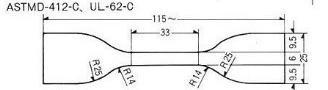
• ASTM D412, Die C Instron 34TM-5
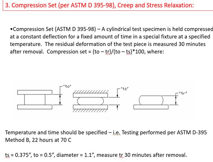
• Compression Set
• ASTM D395, Method B
• 70 hrs, 150 °C
• Abrasion Resistance
• ASTM G195 Taber Abraser Model 1700
• Specimen 4 in. diameter disc
• Friction Test
• ASTM D1894 custom machine
• Specimen 0.78 in. x 1.4 in. x 0.08 in. strip
• Hardness
• ASTM D2240, Durometer (Shore A)
Results and Discussion
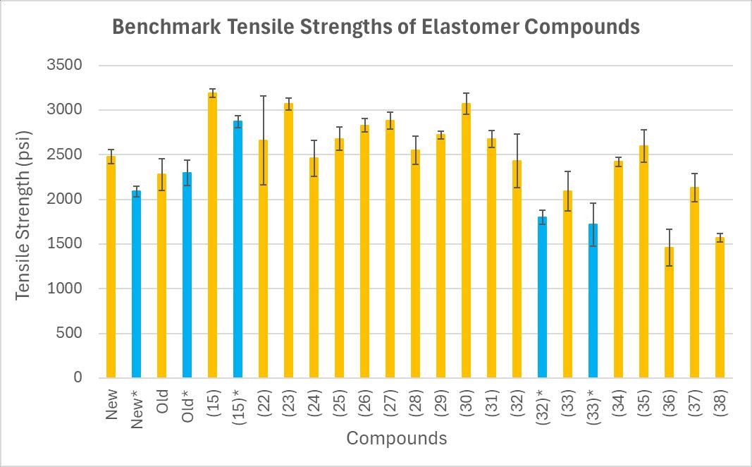
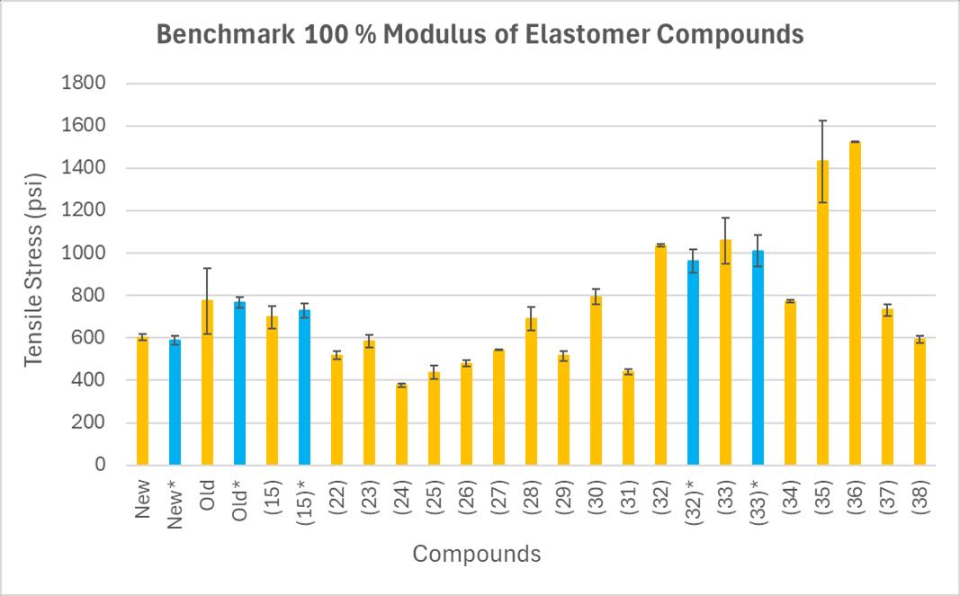
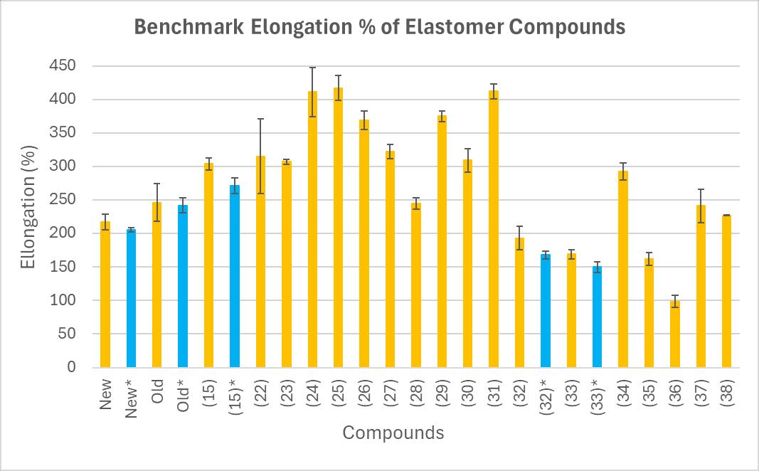
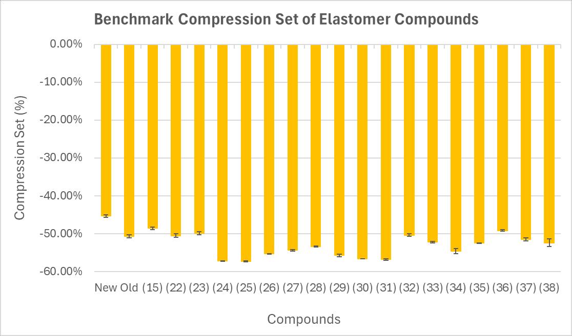
The Figure 2 graphs compare the benchmark tensile and compression set results. Physical properties reported from tensile testing include tensile strength, elongation percent, and modulus at 100% strain (M100). Fluorinated material generally had lower tensile strengths and elongation than their non-fluorinated counterparts. Compound (36) had the lowest tensile strength at 1460 ± 203 psi, the lowest elongation percent at 99 ± 9%, and the highest M100 at 1525 ± 2 psi. (15) had the highest tensile strength at 3190 ± 46 psi while (25) had the highest elongation at 417± 18 %. (24) had the lowest M100 at 376 ± 8 psi. Compared to (22) and (23), M100 was lower and elongation percent higher in (24)-(26) likely due to the internal lubricant. While the tensile strength is similar within this DOE group, the addition of lubricant may have placed (24)-(26) with the highest compression sets seen.
Results and Discussion Cont.
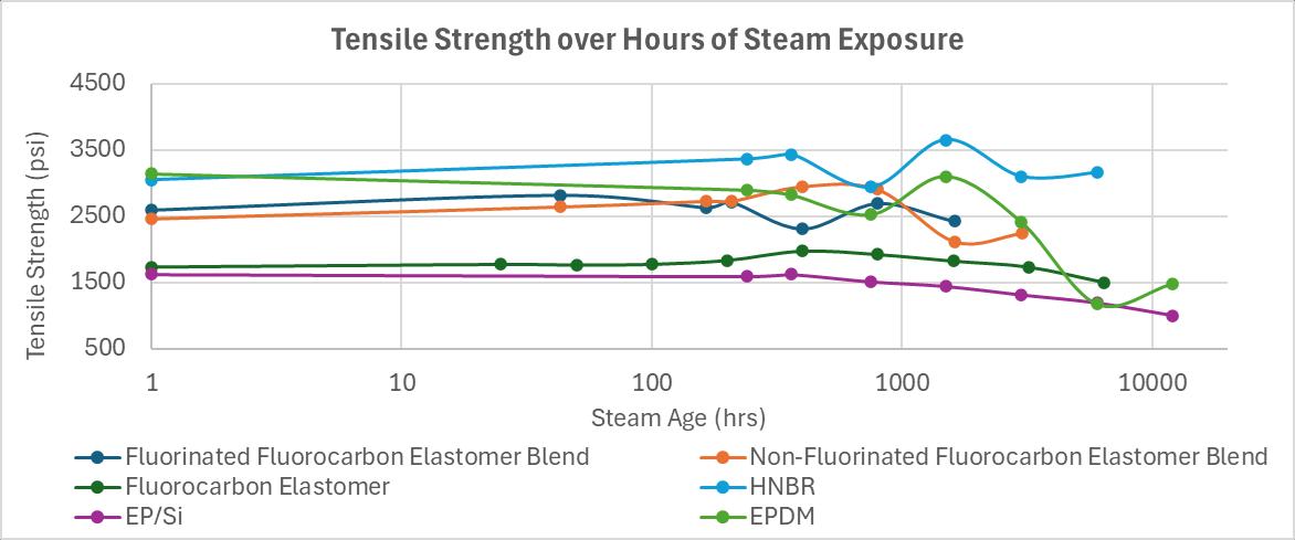
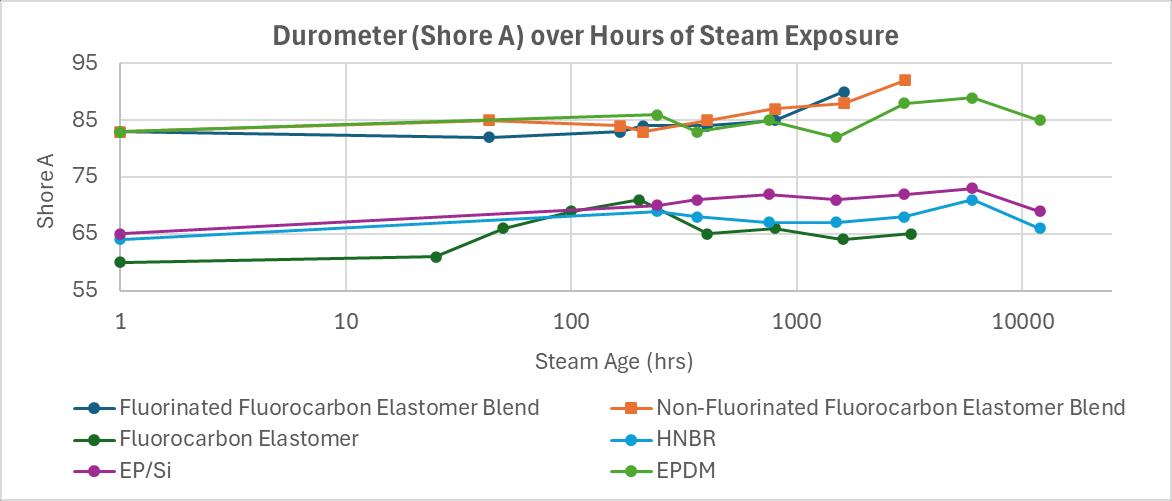
Based on recent benchmark data, we recommended steam aging (15), (23), and (31) up to 6400 hrs. (15) had the highest tensile strength, superior elongation, comparable M100 and compression set. (23) was second highest in tensile strength, superior elongation, lower M100, and comparable compression set. (31) had superior tensile strength, second highest elongation, and third lowest M100. (15) has demonstrated promising performance before, Figure 3 shows 100% HNBR effectively tolerating prolonged steam exposure, qualifying it as the model investigational compound and prompting the current evaluation. Steam aging elastomers hardens them while diminishing tensile strength and total elongation. This study evaluates gasket material optimal for medical devices demonstrating enhanced, consistent physical performance under prolonged pressurized steam exposure. The result is a seal that provides secure containment for high-level disinfection in medical steam sterilizers, preventing pathogen transmission.
References
[1] Rutala, W. A., et al. (2008). Guideline for disinfection and sterilization in healthcare facilities. Centers for Disease Control. https://www.cdc.gov/ infection-control/hcp/disinfection-and-sterilization/index.html
[2] McGain, F., Moore, G., & Black, J. (2016). Hospital steam sterilizer usage: could we switch off to save electricity and water? Journal of health services research & policy, 21(3), 166–171. https:// doi.org/10.1177/1355819615625698
[3] World Health Organization. (2011). Report on the burden of endemic health care-associated infection worldwide. http://apps.who.int/iris/ bitstream/10665/80135/1/9789241501507_eng.pdf.
[4] World Health Organization. (2016). Guidelines on core components of infection prevention and control programmes at the national and acute health care facility level. https://iris.who.int/bitstream/ handle/10665/251730/9789241549929-eng.pdf?sequence=1
Figure 1: Materials testing framework. (a) A non-fluorinated specimen (e.g. tensile) can be (b) fluorinated first or (c) immediately steam aged in an autoclave and pulled out at a specified time to then undergo either a (d) tensile test or (e) compression set test. Specimens for the (f) friction test and (g) abrasion test are not steam aged. Insets in (d-g) show other specimen types.
Figure 3: Previous data comparing tensile strength and hardness of compounds undergone 1 to 12000 hrs of 270 °F steam exposure.
Benchmark
Table 1: Evaluated Elastomers
MRI COMPATIBLE VASCULAR ACCESS DEVICE
Biomedical Engineering Progra��1 and Mechanical Engineering Progra��2 , Gannon University, Erie, PA
Background
The growing demand for advancements in biomedical technology to simplify medical procedures has underscored the need for an MRI-safe vascular access device in the market
This project involves the development of an MRIcompatible vascular access device (VAD) that eliminates ferromagnetic materials, preventing image distortion, enhancing patient safety, and improving procedural efficiency in all MRI environments
Designed for use in radiology departments, hospitals, and emergency care settings, this product aims to provide a two-step MRI-compatible vascular access device
Market Analysis
Globally, the market was valued at USD 1,881 5 million in 2023 and is projected to reach USD 2,647 8 million by 2030, growing at a CAGR of 5% over this period (2)
Proposed Materials and Modules Prototyping
The prototype is designed in Creo Parametric and fabricated using FDM 3D printing with biocompatible polymers for structural components and SLA printing for high-precision features Additionally, silicone compression molding is used for flexible seals, while resin casting techniques ensure durable, MRI-compatible components with controlled material properties
2:
By integrating engineering principles with scientific innovation, the project strives to deliver a safe, efficient, and market-ready solution for MRI-guided vascular access Failure
Stakeholders needs Identified needs
Healthcare professionals
Patients
Medical Device Technicians
•Reduce procedure time
•Reliable under high-pressure conditions
•Long-term efficiency
•Eliminate safety hazards
•Minimize discomfort
•Biocompatible and antimicrobial materials
•Accurate medical results
•Stabilization features
•Non-aggressive vein access
•Compatibility with existing sterilization protocols
•Durable materials resistant to wear and tear
•Clear instructions for use and maintenance
•Intuitive and ergonomic design
Table 1: Customer Needs Identification
Instructions for Use: Two- Step Procedure
Cost and Environmental Impact
The product balances affordability and functionality At an estimated $75–$150 per unit As a single-use device, it prioritizes safety and sterility while minimizing environmental impact through material selection The polypropylene housing and medical-grade silicone components are chosen for their lower environmental footprint compared to traditional stainless-steel alternatives
FMEA Risk Assessment Summary
Catheter dislodgement
Seal leakage
Material degradation
Needle retraction failure
Flow restriction
•Loss of vascular access, procedural delays
•Fluid backflow, contamination risk
•Device failure over time
•Patient injury, MRI interference
•Inefficient contrast delivery
•Secure locking and reinforced catheter attachment
•Compression molding for a tight seal
•PEEK, silicone, polypropylene
•Specific locking mechanism
•Optimized catheter diameter and ≤45° connection angle
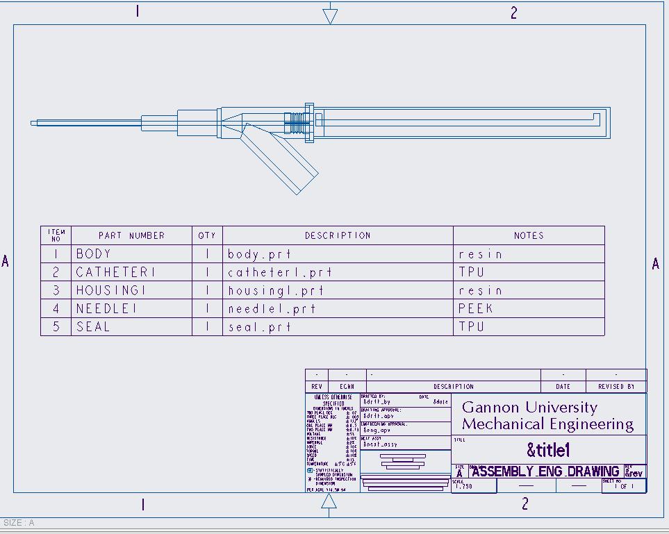
1. Needle module
Made of PEEK for precise insertion with minimal tissue reaction, the needle retracts into a back chamber, locking in a horizontal position during injection for added stability and user control
2. Seal Module
A silicone compressive seal prevents fluid backflow and contamination, maintaining a sterile and reliable system It adapts to pressure changes, expanding for needle entry and contracting upon retraction
3. Catheter Module
The medical-grade silicone catheter remains securely in the vein after the needle retracts It features a standardized connection at an angle of ≤45° to optimize fluid flow and minimize injection pressure
4. Body Module
The bolt-action inspired locking mechanism offers an effortless activation and secure deactivation of the needle, preventing unintended movement and improving one handed usability for practitioners
5. Housing Module
The lightweight polypropylene housing offers mechanical protection while maintaining a comfortable grip, improving durability without compromising ergonomic handling
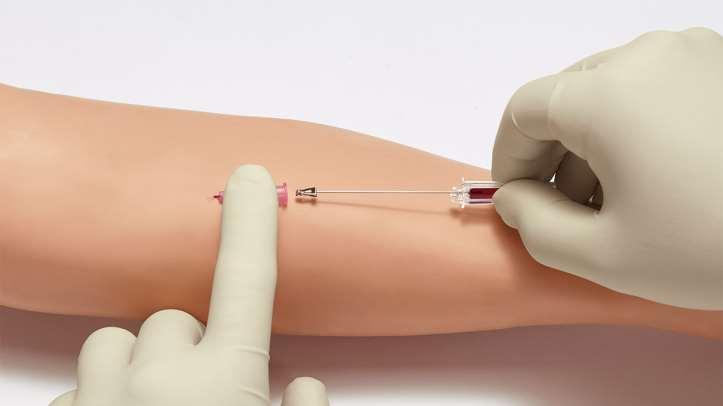
Step 1: Insertion & Locking
Slide the needle into the front locked position using the top pin Insert the device into the patient’s vein Once positioned, retract the needle into the back locked position, securing it safely inside the housing
Step 2: Connection & Stabilization
Attach the contrast tube to the connection port Tape the catheter to the patient’s skin to prevent movement during the MRI scan After imaging, carefully remove and dispose of the device following biohazard protocols
Standards
Compliance
• ISO 10993 – Biocompatibility testing for medical devices.
• ISO 10555 – Requirements for intravascular catheters.
• ASTM F2503 – MRI safety and compatibility guidelines.
• ISO 14971 – Application of risk management for medical devices.
Future Validation
1. Computational Fluid Dynamics (CFD) Simulations ANSYS software will be used to analyze pressure distribution and optimize flow efficiency. Design will be optimized if needed.
2. Mechanical Durability Testing
Structural integrity will be assessed through load-bearing and fatigue tests using Gannon’s Mechanical lab instrumentation.
Figure
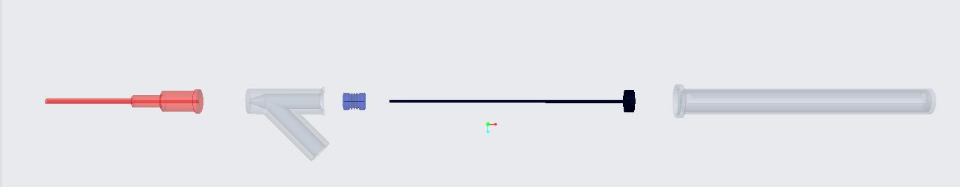
VAD exploded view
Figure 3: Engineering drawing of assembly using Creo
Figure 1: MRI Setting
Figure 4: VAD insertion visualization (3)
Leyre Berganzos Fernande��1 , Jacob Bau��1,2 , Seth Butle��1
Background
Magnetic resonance imaging (MRI) exams are performed to assess potential issues within organs, tissues, and the skeletal system (Figure 1). However, without knowing a patient’s weight, interpreting the images can be challenging. Accurate contrast agent dosing is essential for proper resolution, and without an accurate weight, the MRI resolution may be compromised, making it more difficult to analyze [1].
The scale is designed for patients who cannot be weighed on a regular scale, such as those unable to stand. By incorporating a scale within the MRI, medical professionals ensure that the most accurate weight is used for dosage calculations. The scale’s biocompatibility and the ergonomics of the MRI machine were carefully considered to ensure safety for all users.
Methodology
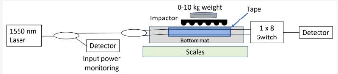
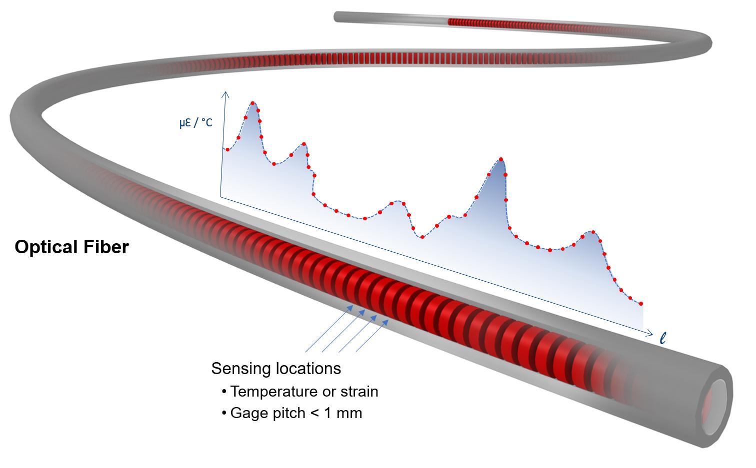
The final design of this system utilizes fiber optic sensors to measure the force a patient exerts when laying on the MRI’s gantry table. Fiber optic sensors can operate within the MR environment and are nonconductive, but highly accurate in extreme conditions [2]. The sensors will operate by detecting changes in light wavelengths before and after a patient lays down on the gantry table (Figure 2).
MRI Scanner Table Scale
Paige Johnson, Jenna Miller, Gregory Coppola, Dr. Xiaoxu Ji
Department of Biomedical Engineering, Gannon University
Design
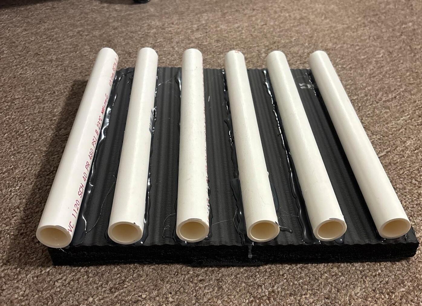
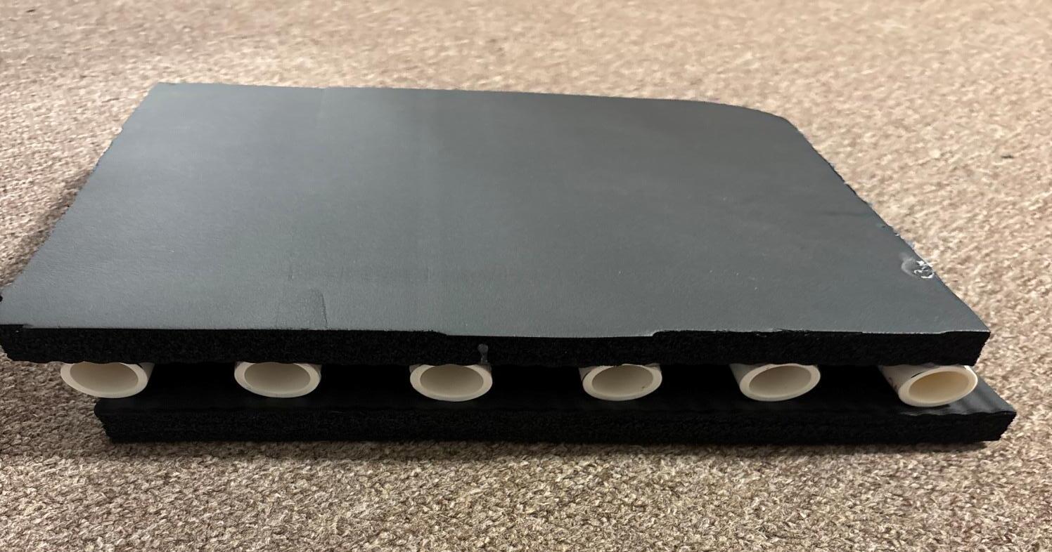
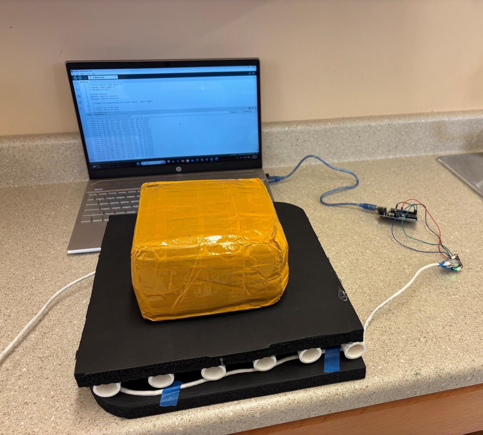
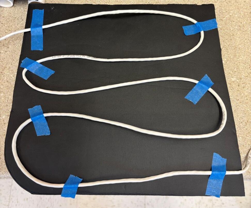
The sensors will need to be assembled and coded to adhere to the force specific calculations before testing can begin. The laser will be used to send light signals though the optical fiber. One rubber mat will be used for the base of the scale and the optical fiber will be adhered to the surface of the first mat (Figure 3). The second mat, which will be referred to as the “impactor”, will have pieces of PVC pipe glued along it and placed on top of the optical fiber (Figure 4). The PVC pipe will allow for the fiber to bend and deform when pressure is applied to produce a wavelength. This wavelength will then be converted into a pressure or force using a photodetector [3].
Procedure
Laser will be used to send a light source through the fiber optic. As force is applied to the impactor, the fiber will deform, disrupting the constant light, causing a change in wavelength. A light sensor will be used to detect this change [4]. The wavelength change will then be converted to a force using an Arduino Uno. From here, an Arduino code will be written to convert the force to a known mass. Different known weights will be used to guarantee the accuracy of the sensor (Figure 5). A test mat measuring 12”x12” was built to test the accuracy of the system, and another mat was constructed to human dimensions.
Discussion
• Once the accuracy of the test scale is guaranteed, this scale can begin trials with larger weights that match human weight.
• Analyzing the accuracy and weight capacity of this scale will allow medical professionals to integrate the table scale into the MRI process.
• The outcome of this study will allow medical professionals to administer accurate contrast dosages.
• Future work can look to test different materials on the impactor or different optical fibers to further improve the overall accuracy of the scale.
References
1. Heiland, S., Reith, W., Forsting, M., & Sartor, K. (2001, September 4). How do concentration and dosage of the contrast agent affect the signal change in perfusionweighted magnetic resonance imaging? A computer simulation. Magnetic Resonance Imaging. https://www.sciencedirect.com/science/article/pii/S07 30725X01003940
2. Su, H., Iordachita, I. I., Tokuda, J., Hata, N., Liu, X., Seifabadi, R., Xu, S., Wood, B., & Fischer, G. S. (2017a, April 1). Fiber optic force sensors for MRI-guided interventions and rehabilitation: A Review. IEEE sensors journal.
https://pmc.ncbi.nlm.nih.gov/articles/PMC5482288/
3. Funnell, A. C., & Thomas, P. J. (2023, January 12). Design of a flexible weight sensor using optical fibre macrobending. MDPI. https://www.mdpi.com/14248220/23/2/912#:~:text=A%20flexible%20weight%20se nsor%20based%20on%20optical%20fibre,and%20small %20fibre%20bending%20path%20lengths%20is%20pre sented.
4. Pendão, C., & Silva, I. (2022, October 5). Optical fiber sensors and sensing networks: Overview of the main principles and applications. Sensors (Basel, Switzerland).
https://pmc.ncbi.nlm.nih.gov/articles/PMC9570792/
Figure 3: Diagram of Layout of Scale
Figure 4: Test Mat Impactor
Figure 5: Mass on top of the impactor connected to light sensor
Figure 2: Wavelength Changes in Fiber Optic Cable
Figure 1: MRI Machine and Gantry Table
Polyurethane Foam to Metal Bond Testing
Ryan
Osche & Brandon Warr
Mechanical Engineering Program, Gannon University, Erie PA
Abstract
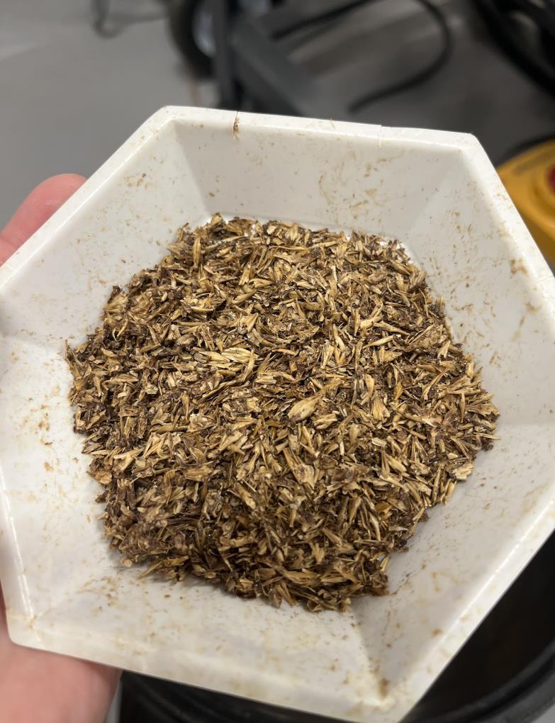
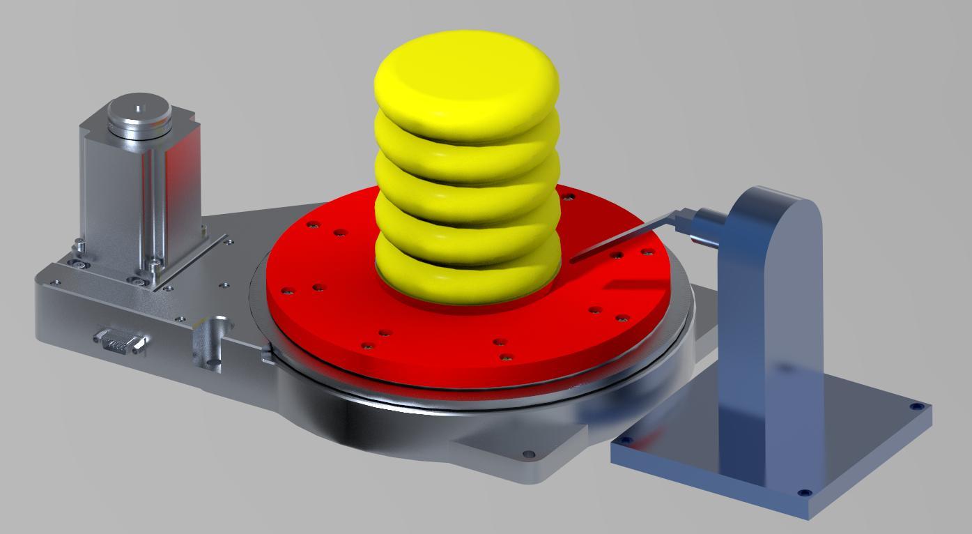
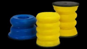
Pleiger Plastics Co. is an engineering company located in Washington Pennsylvania that specializes in creating custom plastic parts for their customers. For our senior design project, our goal is to improve their current method of testing the bond between the polyurethane foam and steel plates of their custom polyurethane springs.
Pleiger Plastics Co. currently has an employee that tests each produced part by hand by wedging a screwdriver into the seam between the foam and the steel. If the screwdriver separates the foam from the steel, the part is considered to be a failed part and is discarded for scrapping. This process is not only inconsistent and inaccurate, but it is also unsafe for the employee. To remove these concerns from product testing, we plan to create a test fixture that will automate the process where the employee only needs to place the part into the fixture and run the test.
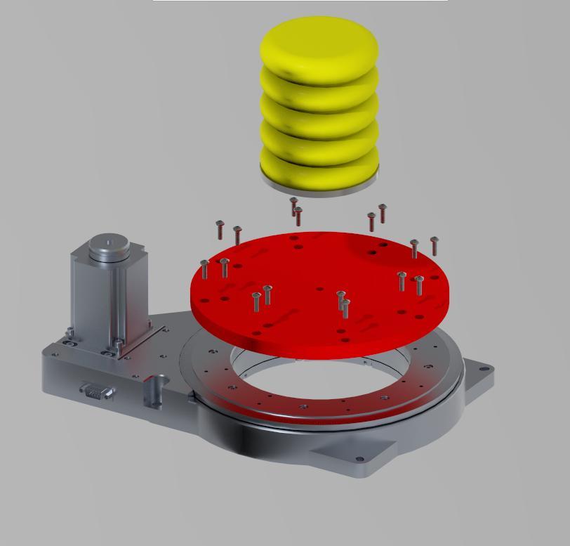
Project Plan
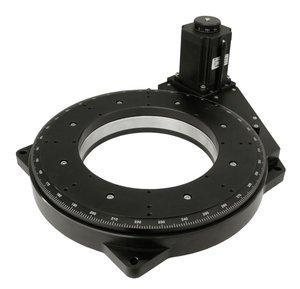
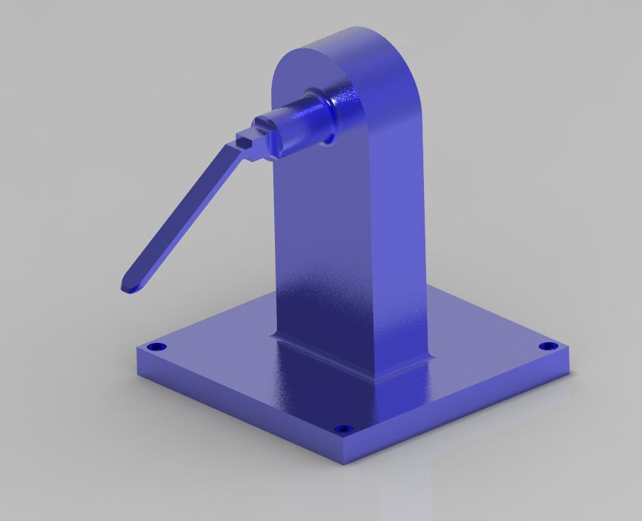
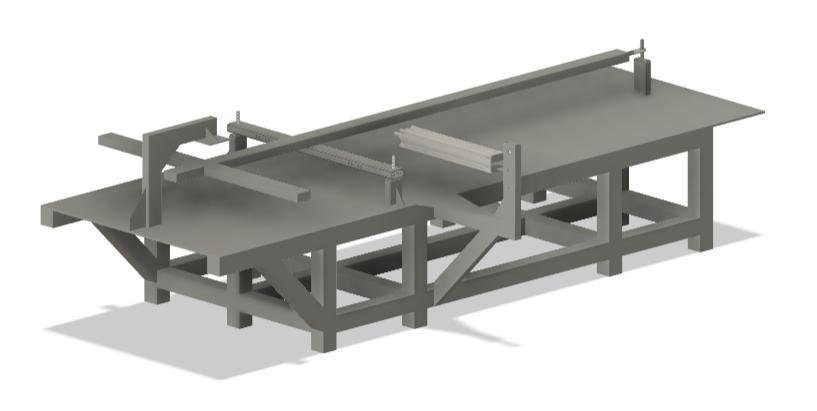
• Purchase/Design programmable rotary table
• Design mounting table to secure PU springs
• Design spring loaded arm to apply force
Project Components
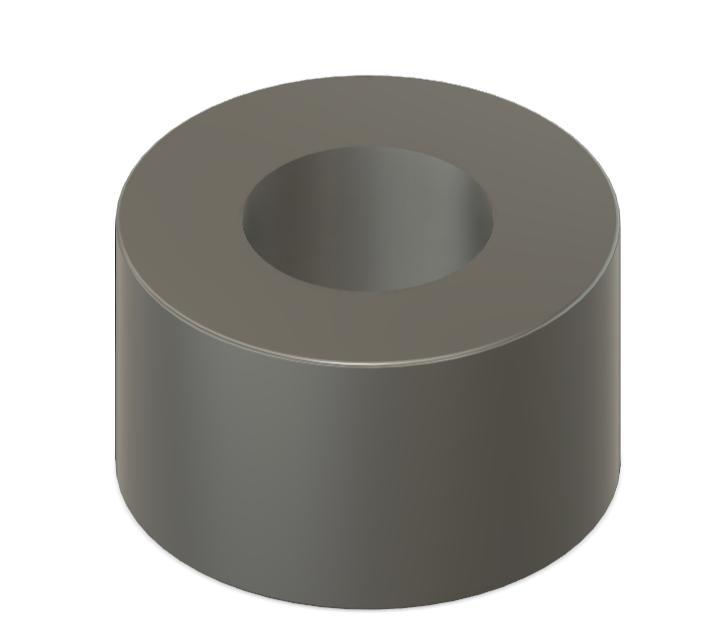
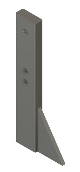
• Rotary Table • Custom Mounting Table
Determine a method to consistently and accurately test the bond quality between polyurethane foam and steel inserts to reduce or remove human involvement and inconsistency in the bond testing process.
Polyurethane Foam Springs
Requirements
• Easy to use/operate
• Accepts parts of all shapes and sizes
• Undamaging to the springs
• Efficiency
• Safety Project Statement
Constraints
• May 5th Due Date
• $800 Budget
• Student Availability
• Varying Spring Shapes/Sizes
Standa 8MRB240-152-59
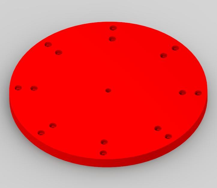
Custom Mounting Table
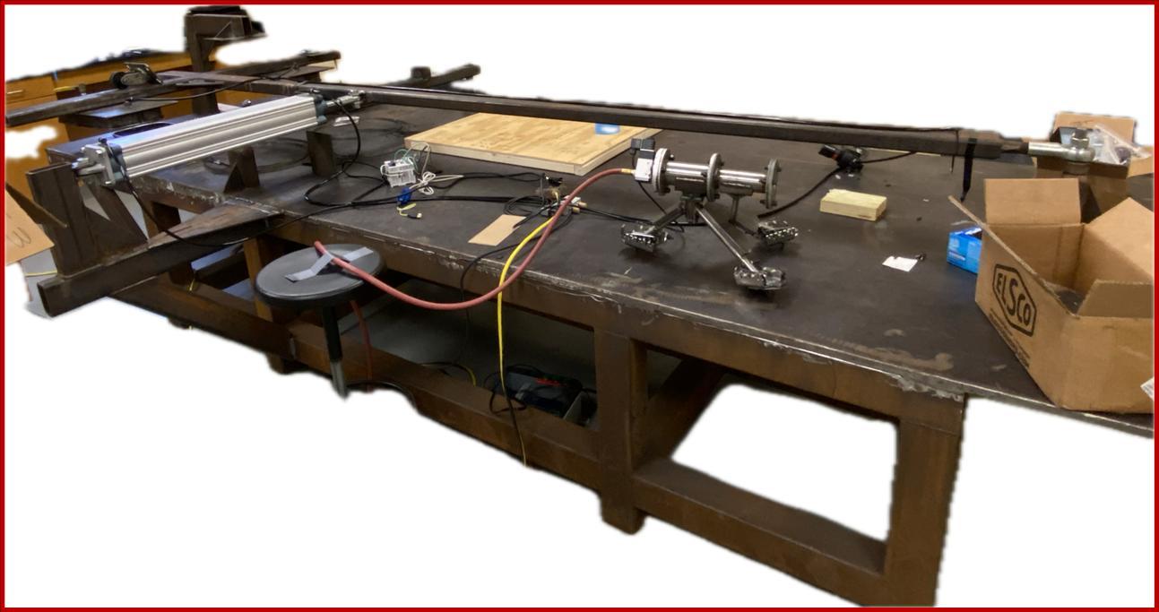
Redesign of Locomotive Traction Motor Boots and Fatigue Tester
1E. Lander, 1G. Markley, 1C. Mullins, and 1R. Michael
1Dept. of Mechanical Engineering, Gannon University, Erie, PA
Fusion360 Models
We used Fusion360 to model design ideas which allowed us to visualize the redesigned fatigue test table for the locomotive boots. This way we can easily make changes and see how they interact with the test rig. It also allows for us to 3D print prototypes of our designs.
Abstract
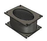
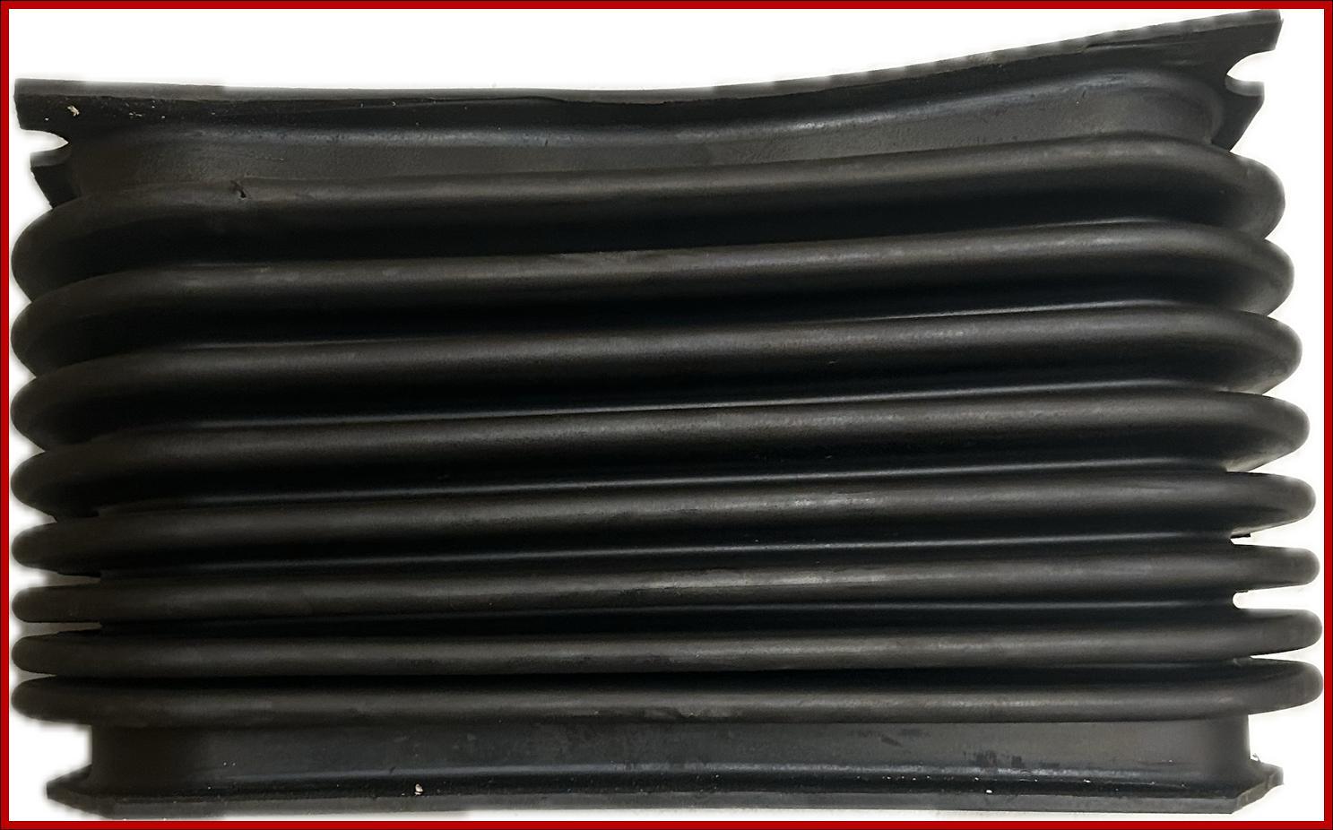
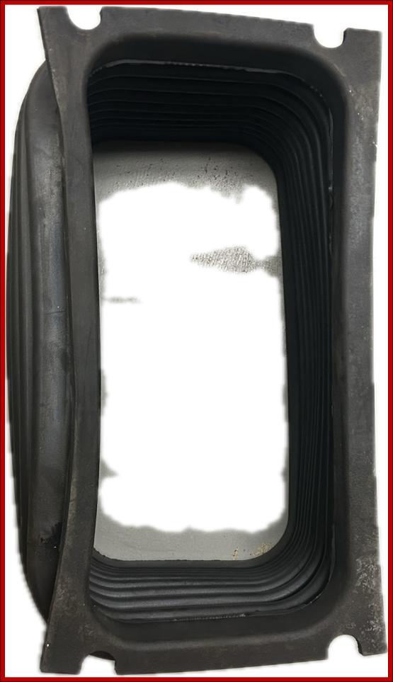
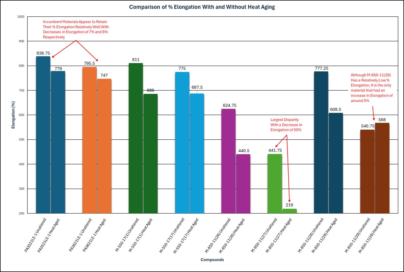
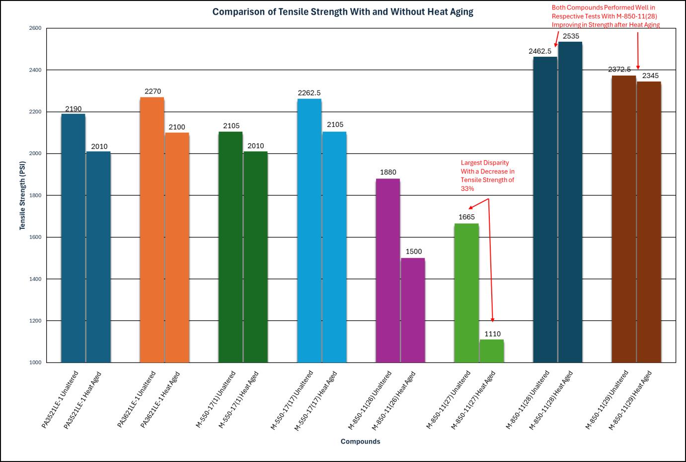
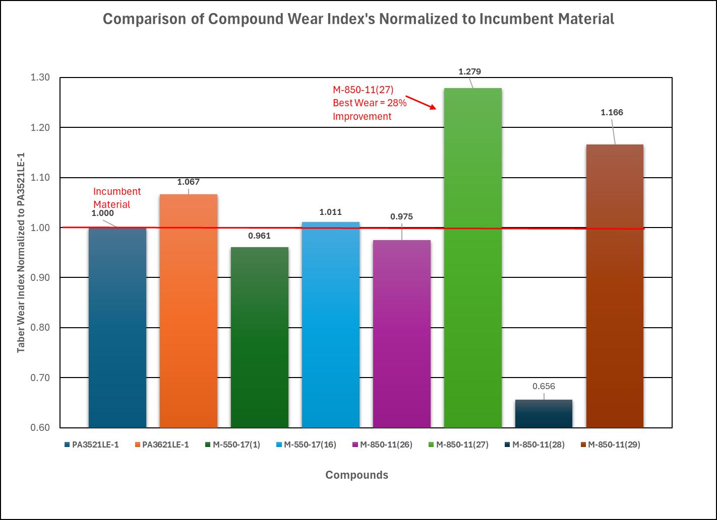
This project aims to enhance Wabtec's testing process of locomotive traction motor boots by redesigning the boot’s fatigue tester. The traction motor boots act as a flexible duct that supplies airflow to the traction motors and allows relative motion between the trucks and the locomotive’s platform. The existing tester is inefficient and difficult to use, wasting valuable time during boot installation and testing. Our improvements focus on making the tester adjustable for easier installation and removal of boots, enabling Wabtec to test various boot designs more effectively and accurately. Additionally, we will explore materials to improve boot durability, flexibility, and resistance to wear, elongation, and extreme temperatures. By reducing testing time and ensuring more reliable results, the redesigned fatigue tester will support the development of higher-performing traction motor boots. Ultimately, these enhancements will lead to cost savings, better product longevity, and increased efficiency in the design and testing process for locomotive boots.
Final Modifications:
• Robust Bumpers that can slide horizontally along pendulum rest to allow for controlled angle of swing.
• Robust spacers which create a vertical displacement corresponding with TM boot purchase spec.
• "Sleeve" design on fixtures that need adjusted vertically such as the actuator support.
• Hydraulic bottle jacks to assist operators in lifting heavy components such as T-bar and T-bar rest.
• Pressure System that records and displays the pressure inside TM boots.
• Emergency Stop has been added to ensure operator safety in case of accidents.
Material Descriptions
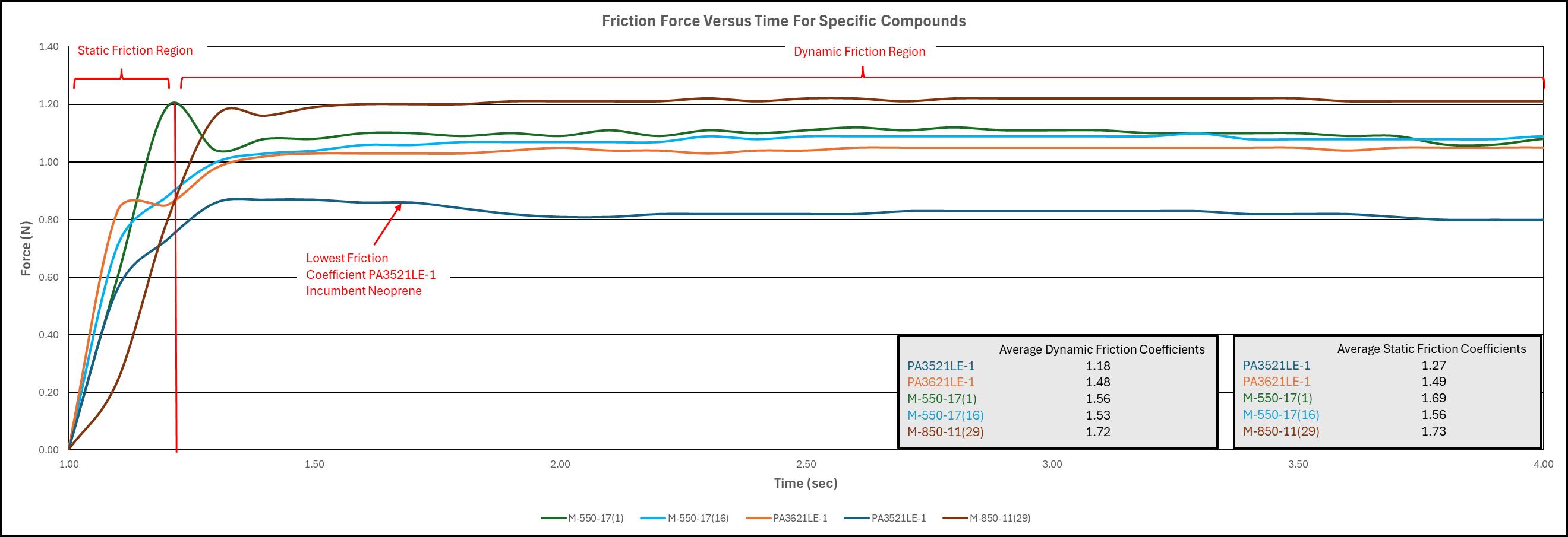
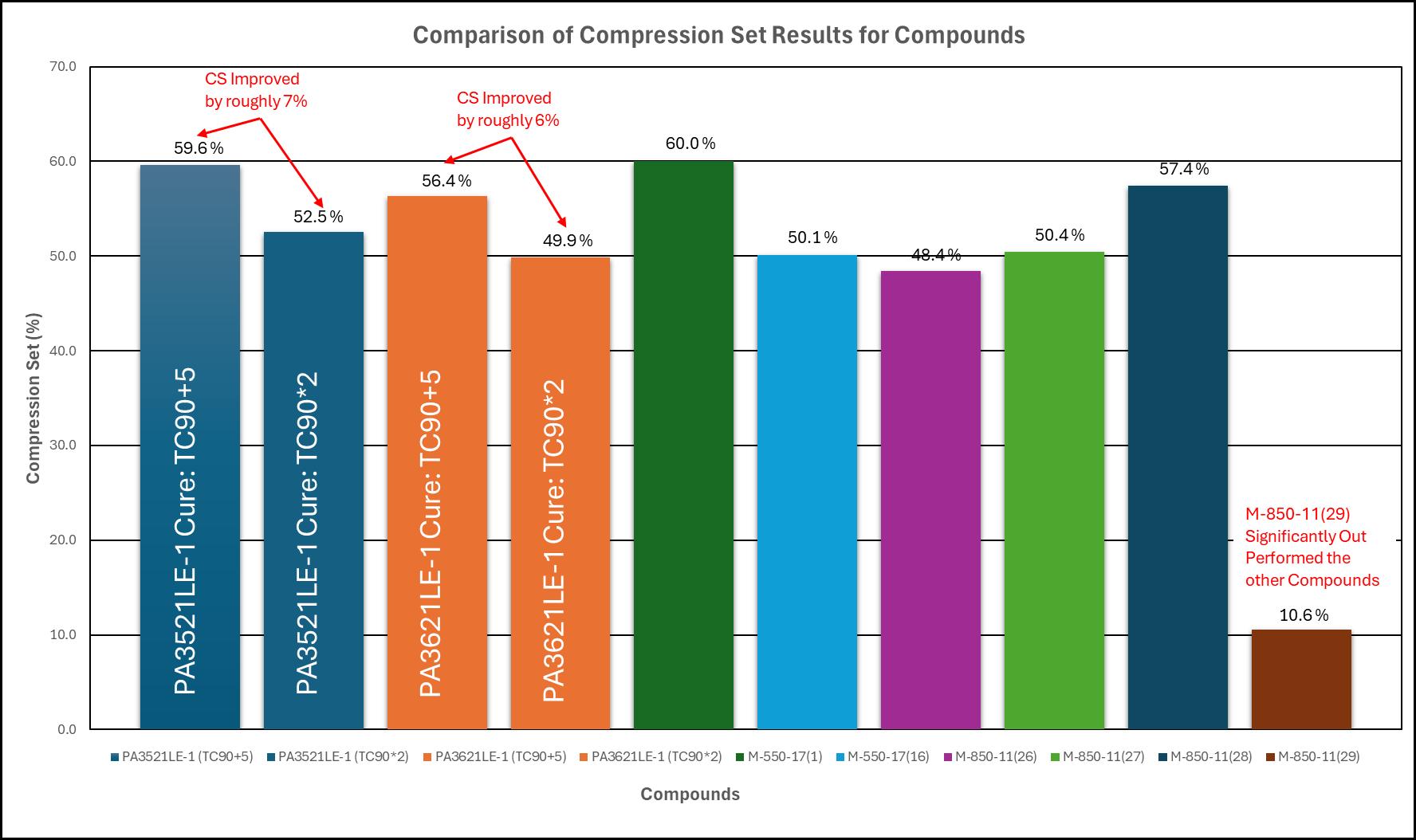
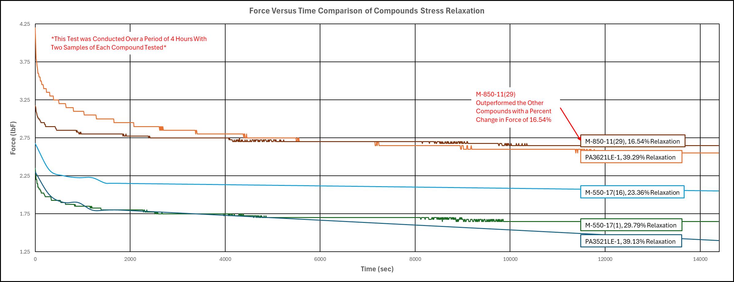
PA3521LE-1 : Incumbent Neoprene, Hexpol Lot #1
PA3621LE-1 : Incumbent Neoprene, Hexpol Lot #2
M-550-17(1) : Original Corry Rubber Neoprene Compound Used in P1 boot Qualification Test
M-550-17(16) : New Corry Rubber Neoprene Compound
M-850-11(26) : Corry Rubber EPDM Compound with ½ Slip Agent
M-850-11(27) : Corry Rubber EPDM Compound with no Slip Agent
M-850-11(28) : Corry Rubber EPDM Compound with no Slip Agent. Fatigue Resistant Cure System #1
M-850-11(29) : Corry Rubber EPDM Compound with no Slip Agent. Fatigue Resistant Cure System #2
Material Testing
To select a potential candidate for a new traction motor boot material, several material tests were conducted to ASTM standards. The tests conducted were:
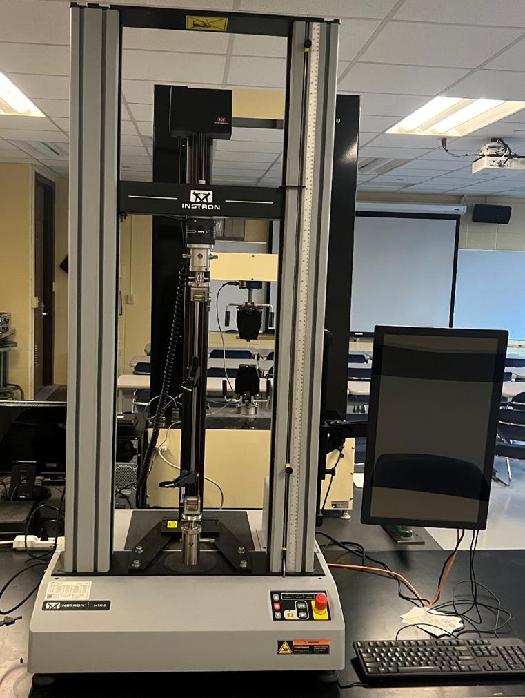
• Tensile Testing (ASTM D412 Method C)
• Compression Set Testing (ASTM D395 Method B)
• Heat Age Tensile Testing (ASTM D573/ ASTM D412)
• Abrasion Wear Testing (ASTM D3389)
• Stress Relaxation Testing
• Friction Testing
The following are results from these tests:
Figure 1: Traction Motor Boot Fatigue Table
Each part went through a series of iterations until a final design was achieved in accordance with Wabtec's requirements.
Cybersecurity, Compter Science, Gannon University, Erie, PA
Abstract
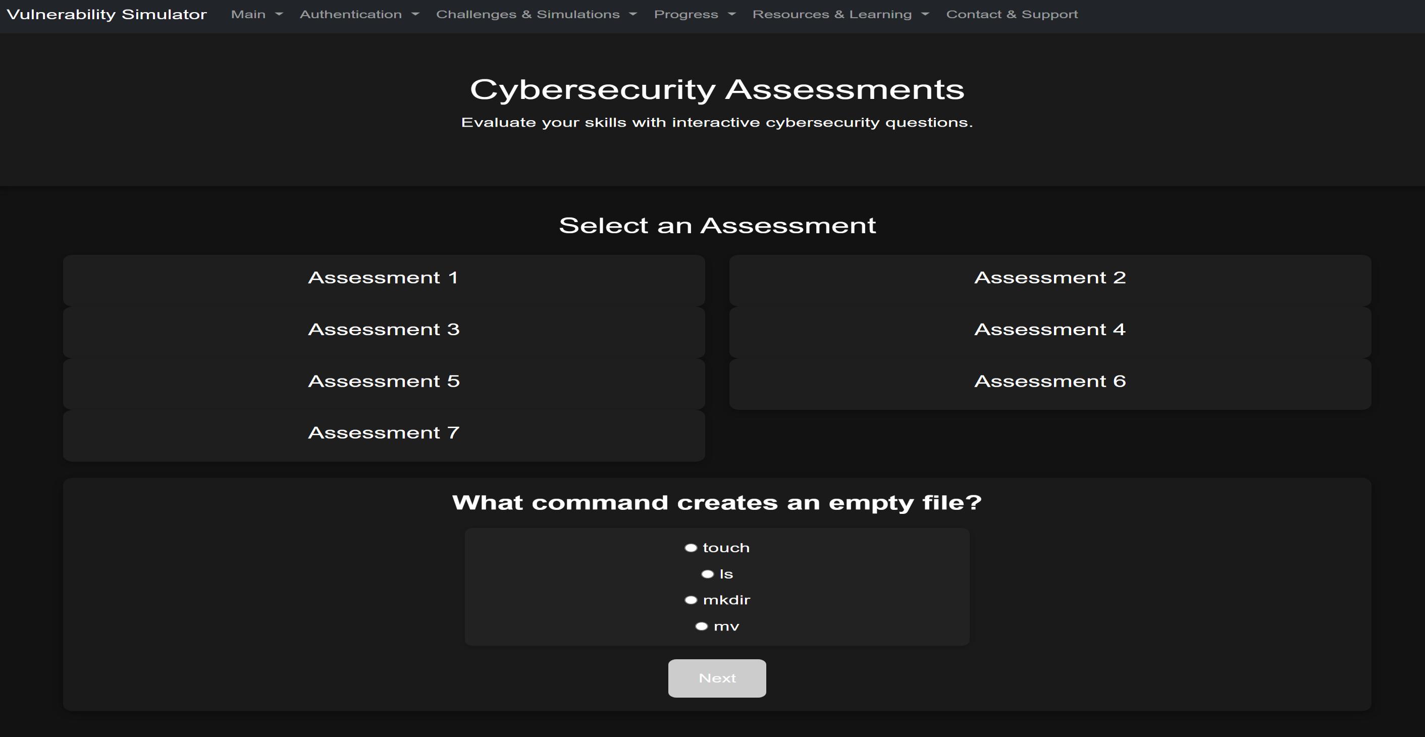
This project aims to develop a Linux-based vulnerability simulator designed to help cybersecurity students enhance their command-line skills. The simulator provides structured challenge sets, allowing users to gain hands-on experience in a controlled environment Each challenge set includes 8-12 progressively structured tasks, guiding users from fundamental operations like file manipulation to more advanced concepts such as working with compressed archives A key feature of the simulator is its interactive terminal-based environment, replacing the initial virtual machine approach for a more efficient and accessible user experience The project also includes a post-lab assessment system, enabling users to test their understanding after completing the challenges. The assessment dynamically adapts to the selected challenge set and provides scoring
Frontend overall: The Vulnerability Simulator features a streamlined and intuitive frontend designed to guide users through every stage of their cybersecurity learning journey. From the authentication pages that securely handle login and registration, to the challenge selection interface that categorizes tasks by difficulty level (Beginner, Intermediate,Advanced), every page is built for clarity and engagement. The simulation pages provide a live terminal environment for hands-on practice, while the progress dashboard tracks user achievements and growth over time.Additional resources and learning pages offer helpful guides, and the contact & support page ensures users always have assistance when needed all wrapped in a responsive and modern UI that supports focus and immersion.
Hands-On Linux Learning
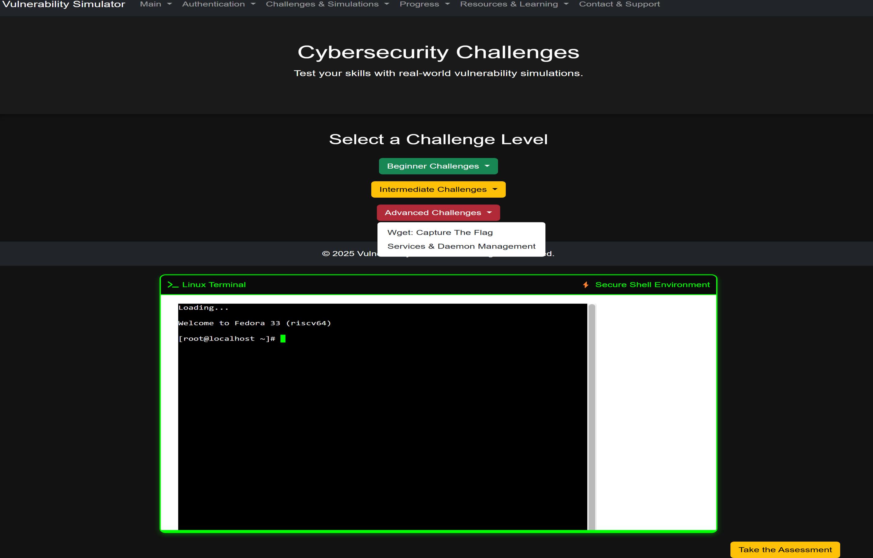
This platform offers a structured and gamified approach to learning Linux and cybersecurity fundamentals through seven progressive challenge sets. Starting from the basics, users learn essential Linux commands like file creation, directory navigation, permissions, and user management. As they progress, they handle compression tools, system monitoring, and real-world administrative tasks. Intermediate and advanced sets introduce more technical scenarios like analyzing processes, investigating logs, or decoding base64 strings building real confidence in a command-line environment. The final sets simulate offensive and defensive cybersecurity roles through CTF-style missions, such as using wget to retrieve data, finding hidden flags, and practicing Red vs. Blue team tactics. These challenges not only teach practical Linux usage but also sharpen critical thinking, threat analysis, and problem-solving preparing users for real-world cybersecurity labs, internships, and careers.
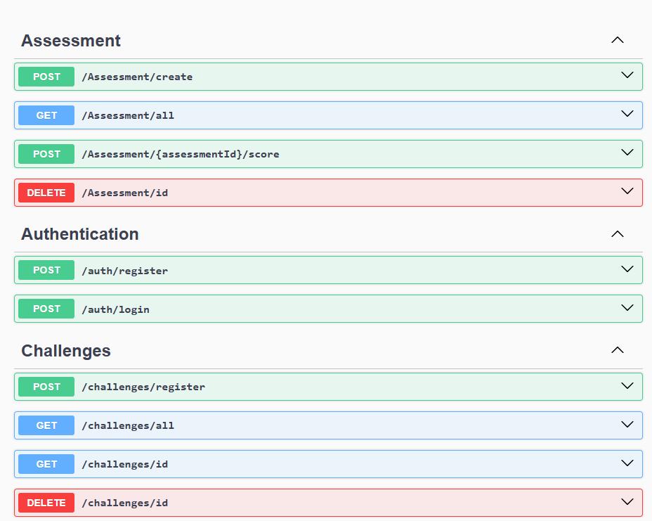
The backend for the Vulnerability Simulator project is built in a simple and organized way that makes it easy to understand and work with. It uses clear layers to keep things clean. TheAPI handles requests, the services do the logic, and the database layer takes care of saving and loading data. Assessments are linked directly to specific challenges, so you can build quizzes that make sense for each topic. When a new challenge or assessment is created, the system sends back the ID right away, which makes it super easy for the frontend to keep track. Scoring is done instantly when someone submits an answer. Password handling is secured using BCrypt, and all inputs are validated before being stored.
Technology Used:
• C# withASPNET Core webAPI for backend logic
• Bcrypt for Password Encryption
• SQL Lite DB Browser
• Fluent Result for
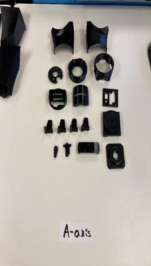
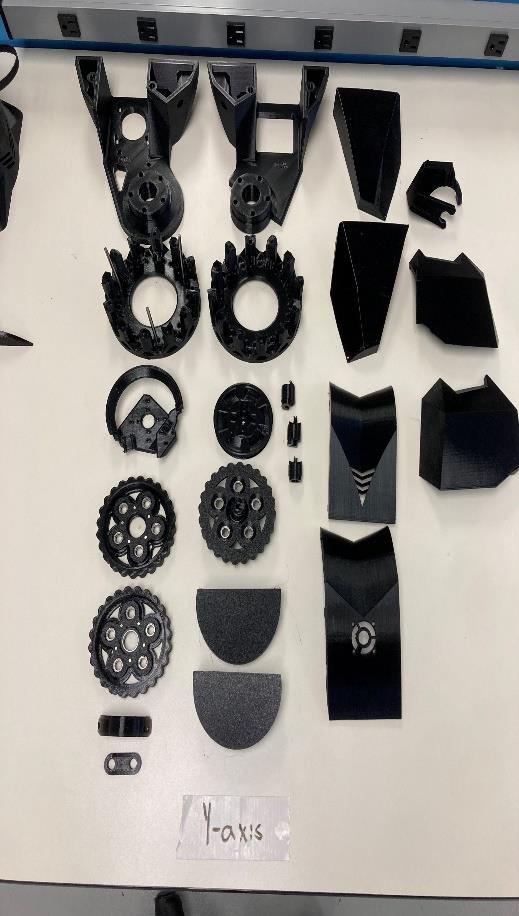
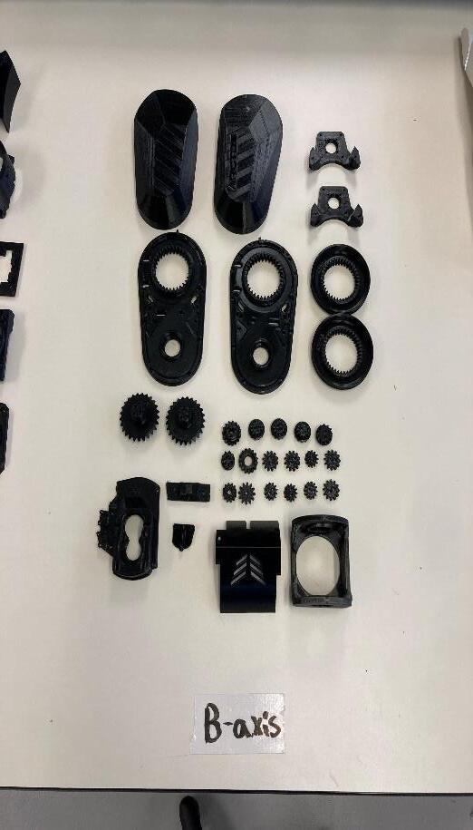
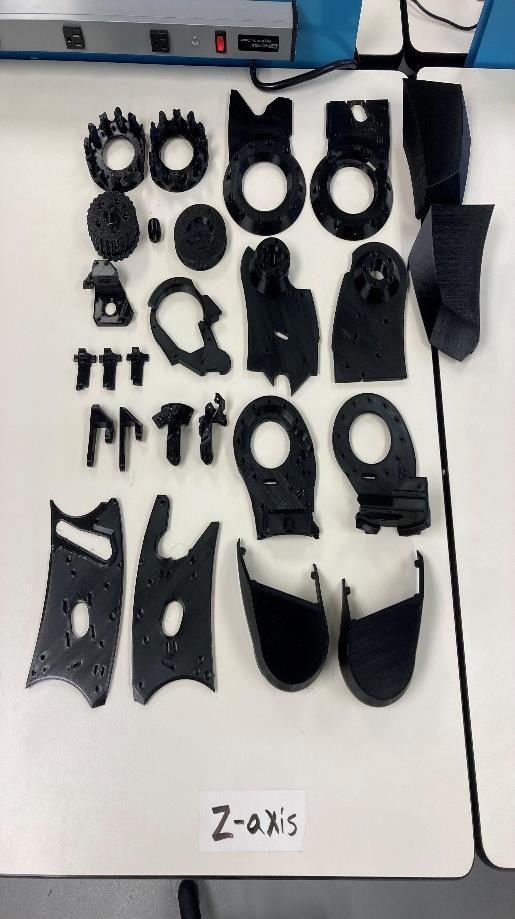
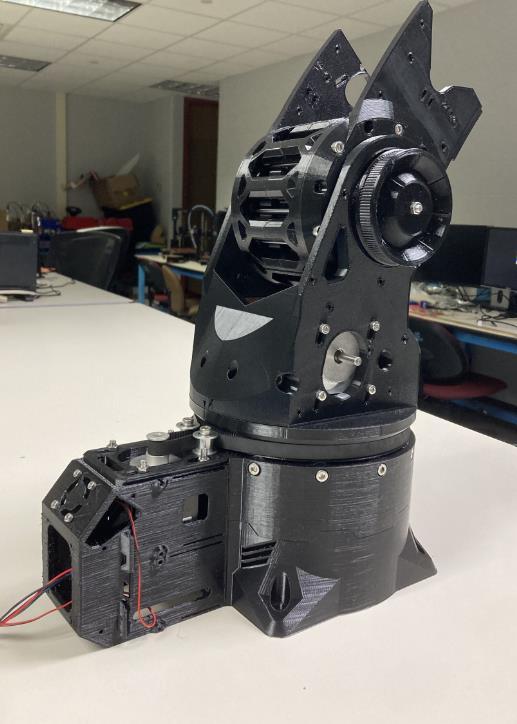
Wheelchair Mounted RoboticArm
Abstract
In this poster, we present the design and development of a cost-effective, wheelchair mounted robotic arm aimed at enhancing accessibility and independence for individuals with mobility impairments. Our approach integrates a custom designed, user-centered control system to ensure intuitive operation and adaptability to individual needs.Additionally, we engineered a power distribution system that enables the robotic arm to operate efficiently by using the wheelchair’s existing battery system.Akey innovation of our project is the utilization of an open-source robotic arm design, allowing us to use 3D printed components and replace high-cost materials with more affordable alternatives. This method significantly reduces manufacturing costs while maintaining functionality and reliability. Our prototype demonstrates the feasibility of low-cost, assistive robotic technology and serves as a foundation for future refinement and potential commercialization. By making advanced assistive devices more accessible, this project contributes to the ongoing effort to improve quality of life for individuals with disabilities.
Project Objectives
• Utilize additive technology
• Assemble robotic arm properly
• Mount the arm to the wheelchair
• Design and make controller for the arm
• Utilize wheelchair batteries for power
• Seamlessly integrate all components
• Final assembled arm can complete basic tasks
• Do not exceed a budget of $1000
Christopher Petteys, Joseph Kvortek, Nicholas Nagy petteys001@gannon.edu, kvortek002@gannon.edu, nagy005@gannon.edu
Advisors: Mr. Jack Little, Dr. Ramakrishnan Sundaram little018@gannon.edu & sundaram001@gannon.edu
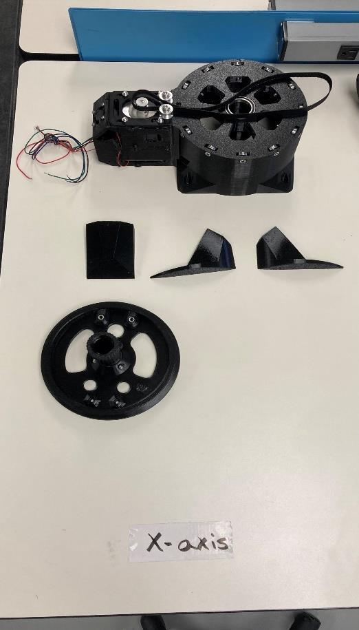
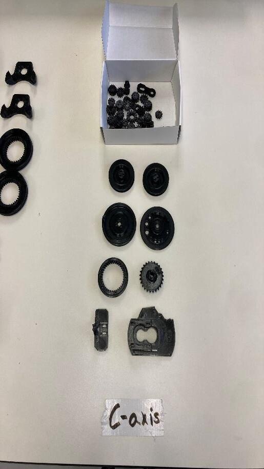
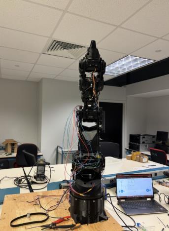
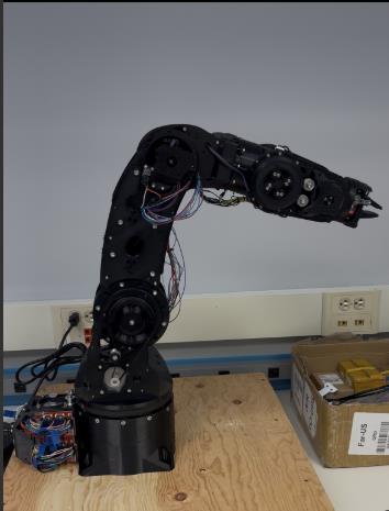
Assembly ofArm and Mounting Bracket
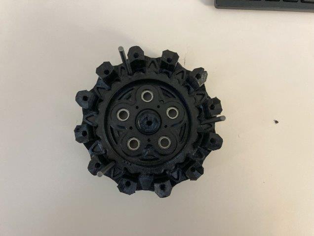
3D Printing &Assembly
• Open-source robotic arm design from ARCTOS
• 3D printed all components using PETG filament
• 6 degrees of freedom
• Max reach: 2 feet
• Payload Capacity: 1.1 lbs.
• Gear boxes: 5
• Wire connections: 80
• Electronic devices: 19
• Stepper motors: 6
• Servo motors: 1
• Hardware parts: 742
• 3D printed Parts: 135
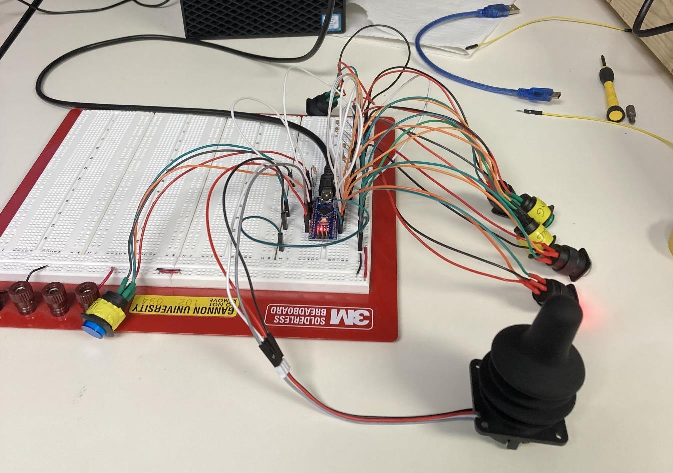
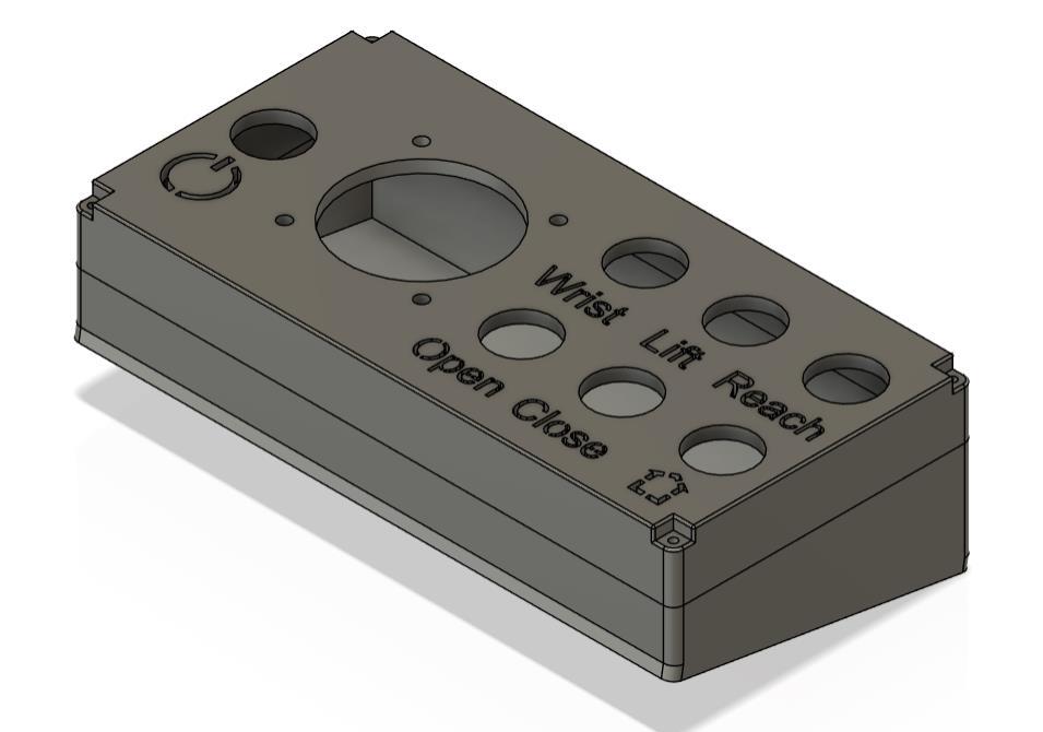
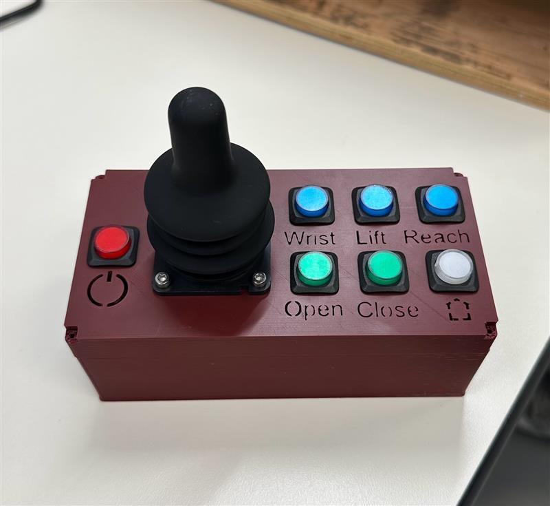
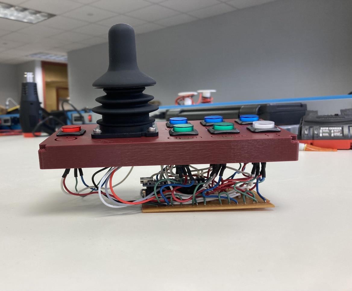
Controller
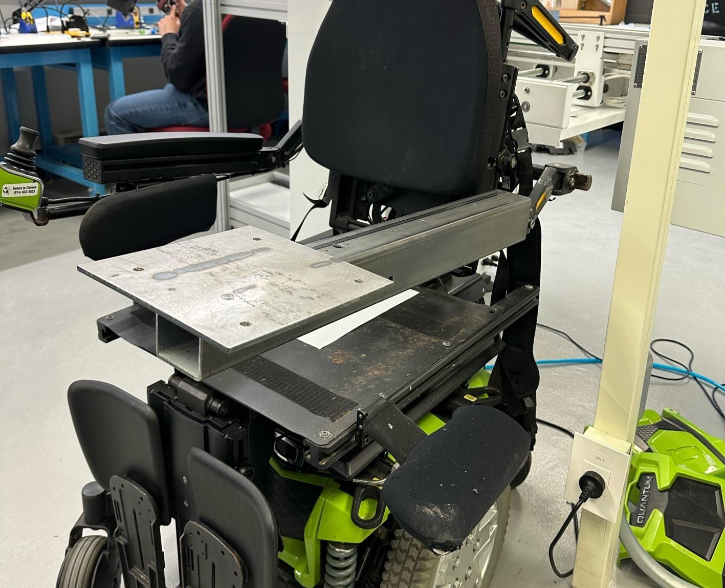
Mounting Bracket
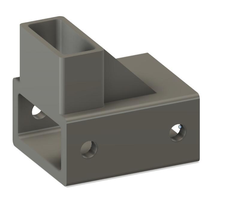
• 2.75” x 2.75” x 24” steel tube welded to an 8” x 8” steel plate
• Attached to wheelchair arm with four 3/16” stainless steel screws
• Holds robotic arm, controller, and E-Stop
• All wire connections ran through the interior of the steel tube
• Controller is custom designed for our robotic arm
• 3 modes of operation, ability to open and close the gripper, a homing option for the arm, and a power button to turn on the controller
• The code was developed by our group
• The code acts as a state machine to determine the operating mode so there is no overlap
• Designed to incorporate a wheelchair joystick to ensure ease of use for the user
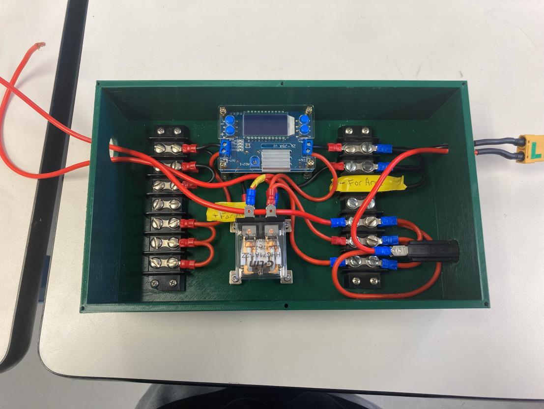
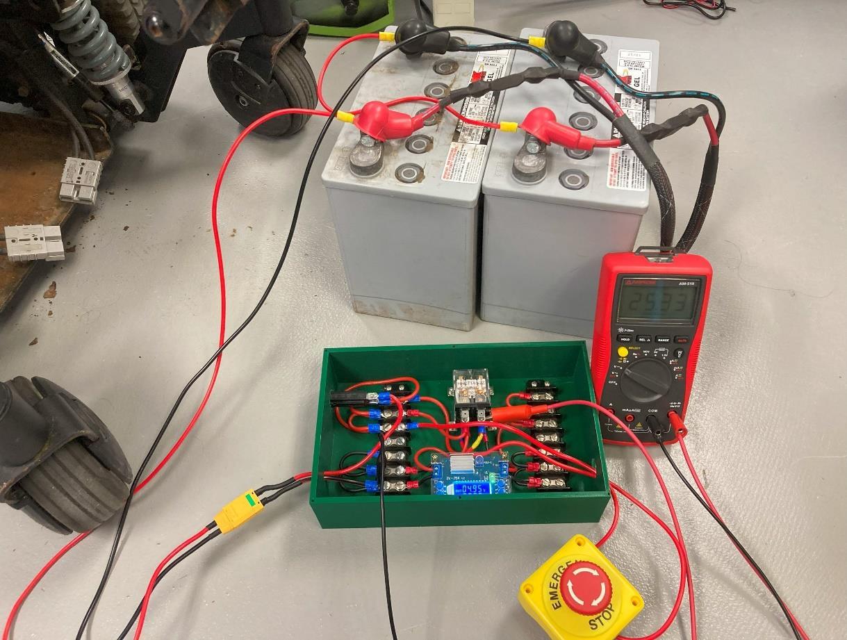
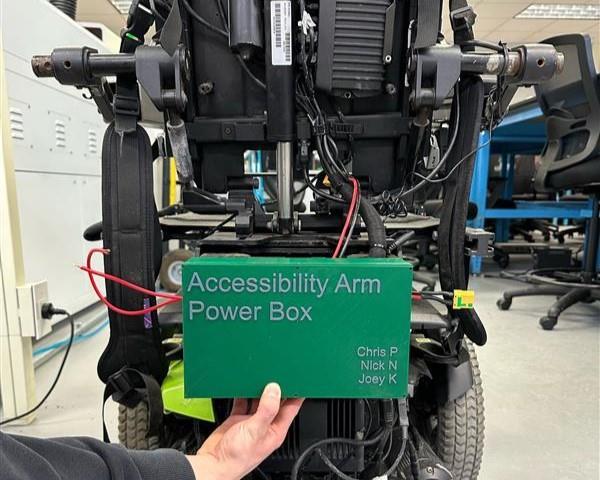
Power Distribution System
• Two 12V wheelchair batteries are wired in series to supply 24VDC to the robotic arm
• Programmable DC-DC Converter inside Power Box that steps down the incoming 24VDC to 5VDC to power the microcontroller in our controller
• DC relay that allows for the E-Stop to shut power off to the entire circuit
• 15Afuse that limits the current draw of the arm to prevent potential damage to components
Conclusions
• Final cost for arm was $930
• Proof of concept for an affordable, assistive robotic arm is demonstrated to be feasible based on our approach
• Lowers barriers for individuals to access assistive technology
• Thanks to these individuals who helped make this project possible: Jack Little,Adam Riesdorph, Dr. Ligo, Dr. Zhao, Dr. Lee, and Dr. Ramakrishnan
WiseShare Properties
AliArthur,Aryan Pashuparthy and Spandana Pagadala
Computer Science, Gannon University, Erie, PA
Abstract
As real estate prices continue to rise, many people are looking for ways to invest in property but are held back by high capital requirements and complex traditional investment processes. The cost of purchasing entire properties makes real estate investing inaccessible to the average person, limiting opportunities for wealth building WiseShare seeks to bridge this gap by offering a simple and flexible solution through fractional ownership. Instead of requiring large sums of money to buy a whole property, investors can purchase smaller shares, allowing them to participate in the real estate market without the financial burden of full ownership
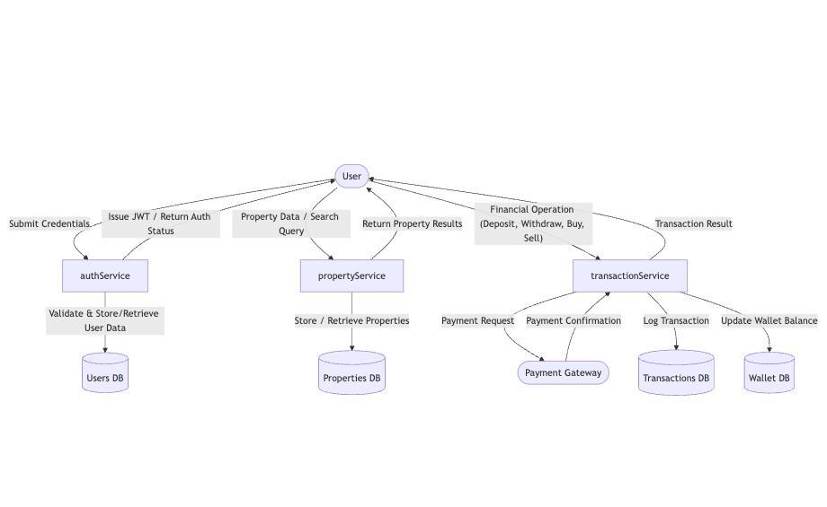
To achieve this, we are developing a web application that provides users with a seamless platform to invest, manage, and track their real estate shares. Our application is designed to be intuitive and user friendly, ensuring that investors, whether beginners or experienced, can navigate the platform with ease
Top of the line payment processing
WiseShare uses Stripe, a secure platform trusted by millions worldwide, to process payments. We ensure your payments are protected through PCI-DSS compliance, tokenized data, and fraud prevention, so you never have to worry.
Modern FrontendArchitecture
The frontend of WiseShare is developed using React js and Stripe js to create a modern, responsive, and user-friendly interface React js enables the dynamic rendering of components, smooth navigation, and real-time interactivity, enhancing the overall user experience Stripe js is integrated for secure and efficient online payment processing, ensuring trust and reliability in financial transactions. This combination of technologies allows WiseShare to deliver a seamless digital platform that supports its mission, making fractional real estate investment more accessible, transparent, and straightforward for users of all experience levels.
Discussion
•WiseShare ensures top-tier security by using Argon2, one of the most secure password hashing algorithms available. Argon2 is designed to resist bruteforce attacks by incorporating time, memory, and parallelism hardness, making it extremely difficult for attackers to compromise sensitive information All passwords and critical data are securely hashed and encrypted before being stored, ensuring that user credentials remain protected. By implementing industry-leading encryption practices, WiseShare guarantees that your personal and financial information is safe, giving you peace of mind and eliminating any concerns about unauthorized access or data breaches.